

This is a companion post for my YouTube video on creating a WLED lit Christmas tree from an original pre-lit, three section artificial tree.
Our original Christmas tree came pre-lit. The basic remote allowed only two selections.. all white or multi-color (well, I guess three since you could also turn on both the white and multi-color lights).

Requirements
If I was going to restring the tree with my own lights, there were some requirements that I wanted to meet:
- Lights should be permanently installed. I did not want to have to add the lights and remove them each time the tree was put up and taken down... just like the pre-lit version.
- Parts, or light sections, should be replaceable in the event of failure down the road.
- Ability to automate. Have the tree lights come on and go off on a schedule.
- For this year (2021), I wanted to add the ability to have the lights react to sound.
Parts List
As always, I begin with the parts that I used to accomplish the project. Note that in many cases, you could substitute different parts to meet your own particular goals.
|
QTY |
DESCRIPTION |
|
1 |
|
|
1 |
|
|
1 |
|
|
1 |
|
|
1 |
|
|
1 |
|
|
1 |
|
|
1 |
|
|
1 |
|
|
1 |
|
|
1 |
|
|
1 |
|
|
1 |
|
|
1 |
Assorted Wago Connectors (optional) |
|
1 |
12V to 5V step down converter (only if
building your own controller) |
Note: Some of the above links may be affiliate links. While this does not impact your cost, the blog may earn a small commission from your purchase.
A few additional notes about the parts:
I used a total of 500 pixels. The tree I was decorating was a 7' tall tree and 500 pixels were the perfect number. You may need to adjust based on the size of your tree.
For this project, I opted to use a pre-built WLED controller... the QuinLED Dig-Uno Controller. This controller, built by Quindor and sold directly by him internationally and by DrZzs here in the US, adds fuse protection, includes a logic level shifter, can be powered by either 5V or 12V and more. The DigUno also comes with the ESP32 with WLED preinstalled! Of course, you can always build your own controller (Quindor's Dig boards are often out of stock and hard to come by at times... especially around the holidays). If you are interested in how to build your own WLED controller, I have both a separate YouTube video and blog post on building the controller. Note however, if you are using 12V lights (as I am here) you will need to either power the controller by a separate 5V power supply, or use a step-down buck converter to step down the 12V power supply to 5V for the controller. If you use a separate 5V power supply, you must connect a common ground between the controller and the pixel strips.
The Control Board

I opted to use terminal blocks and mount all the components on a small piece of wood. This is just to try to keep everything neat and to make it easy to store the entire setup between holidays. The actual wiring is pretty simple:

There are two 12V power leads that will be used to supply power at both the beginning and end of the pixel strips. Called 'power injection' this is necessary to overcome voltage drop and to maintain both brightness and color accuracy throughout all 500 pixels.
Bench Testing
Before stringing your lights on the tree, I'd highly recommend doing a bench test.

Build your controller (or at least a temp version) and connect all of your separate light strings together. My run consisted of 10 strands of 50 pixels each. The signal line from the controller only connects to the beginning of the run, but connect the 12V power at both the start and end of the run.

For the beginning of the run, the easiest way is to use a male JST connector. Connect the signal from the DigUno (or your own controller) to the green and the 12V to the red (+) and white or black (-) wires:

At the end of the run, just connect 12V. The end of the strip should have additional wires for connecting a power injection run. Just be sure to carefully check the (+) and (-)... don't reverse these!
Remember that when WLED starts for the first time, it only lights up the first 30 pixels by default. Don't panic when this happens to your install and think something is wired wrong or your pixel strings are faulty! Just go into the WLED settings -> LED Preferences and set both your power supply voltage and the total number of pixels in your string. For full information on setting up WLED for the first time, see the official WLED wiki.
Play around with a few colors and effects in WLED. Assure that all pixels are lighting and everything works as expected. At this point, disconnect everything and you are ready to string your lights on the tree.
Stringing the Lights on the Tree
This may be the most difficult and time-consuming portion of the entire project! Not only do you need to try to space the rows evenly as you go around the tree (for best effects), but if you want to leave the lights on the tree during storage and your tree comes in sections, then you need to assure that one strip ends at the top of one section of the tree and the next strip begins at the bottom of the next. This is necessary so that you can disconnect the JST connectors between sections when tearing down the tree.
Important Note: The pixel strips have an "in" and and "out", since the data signal only runs one direction. Be sure you are starting your strip at the bottom of the tree with the "in" end of a strip. This is normally a female JST connector, but check your strip documentation to be sure. You don't want to string the entire tree only to find out the strips are "backwards"!

This is how my tree worked out. The red and black wires up the center of the tree are for power injection at the top. I'll talk about that shortly. But this step took me a number of tries to get the lights spaced properly and so that a section ended and began between parts of the tree. Once everything was aligned the way I liked it, I then marked the center pole of each section with yellow tape so that I could easily realign the sections when putting the tree back together the following year.

I also stuck some yellow tape on the JST connectors that would need to be separated so that they would be easy to locate and to assure I didn't disconnect the wrong ones during disassembly.


These snap over the tree branches and wiring and hold everything in place.
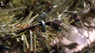
If you don't have clips similar to this, you can use small black zip ties to attach the wires to the tree branches.
Power Runs
As mentioned, we need to get a 12V run to both the start of the strip at the bottom of the tree and to the end of the strip at the top of the tree. The bottom voltage will be along side the data line and will plug into a JST connector at the start of the strip. However, for the top, we will need to run a power line up the center of the tree and attach it to the center post with zip ties. But like the pixel strips, the power connection needs to come apart between the sections of the tree. For this, I soldered one half of a 12 gauge 2 pin wiring harness to the lead wires.

This gave me a secure, but quick disconnect of the 12V wiring when taking the tree apart.

There is also a quick connect at the base of the tree for connection back to the power supply.

Final Connections and Future Disassembly/Re-Assembly
Once the connections between sections of the tree are complete, all that remains to be done is connect the controller leads to the tree. As shown in the photo above, this is just two connections... the 12V power to the top of the tree and a JST connector to the bottom with 12V and the data signal. I created the following diagram that reminds me of the steps I need to disassemble and reassemble the tree between seasons.

All that is left to do is power up the controller and enjoy the season with over 100 different lighting effects, preset, playlists, etc. And since WLED is now natively installed in Home Assistant, automations can be created for your tree. One simple example is to have the tree power on and off at certain times.
Adding Sound Reaction
If you want your tree to 'dance to the beat', you can install the sound-reactive version of WLED to your D1 Mini or ESP32. You will also need to add a microphone (I recommend the Adafruit MAX9814). The DigUno contains breakout pins on the board (A0, 3.3V and GND) for connecting the microphone. The D1 Mini or the ESP32 can easily be removed from the assembly for flashing. I talk more about installing WLED onto the controller in my video Building your own LED Light Controller. I also cover a bit more about the Sound-Reactive version of WLED in my video comparing the ESP8266 and ESP32 with Sound-Reactive WLED.
Have a great holiday season!
Links
Here are the links mentioned within this article:
ESP8266 vs. ESP32 With Sound-Reactive WLED:
Sound-Reactive LED Floor Lamps:
Supporting this blog and related YouTube channel
If you'd like to support future content on this blog and the related YouTube channel, or just say thanks for something that helped you out, you can use any of my Amazon links to make a purchase at absolutely no cost to you. Or if you prefer to say thanks directly, you can buy me a one-off cup of coffee at:
No comments:
Post a Comment
To help eliminate spam and to keep all conversations civil, submitted comments are moderated. Therefore your post may not show up immediately. Please be patient as most reviews are completed within a few hours.