

This is a companion article for my YouTube video on building a simple motion-activated LED strip controller that does not require any additional automation software and will work as a standalone system.
I've created other videos and blog articles on building LED controllers, the most popular being Motion-activated Stair Lighting without Staircase Modification. I had one of my YouTube channel subscribers reach out and ask if a system could be made that didn't require a home automation system, like Home Assistant, to function. Basically, could a simpler system be created that would work without any additional systems or hardware.
After tinkering around, I came up with the following. Note that this is a very basic system. It simply uses one or two motion detectors to turn the LED strip on when motion is detected and shuts the lights off after a user-specified amount of time. There are no fancy effects like with the popular WLED... you can only select a single color for the light strip and an overall brightness. But once setup and configured, nothing else is required. You don't even need wifi after the initial setup, except to update the application or change the settings.
Parts List
The parts list for this project is very similar to the list for the Build Your own LED light strip Controller, but there are some minor changes and some variations if you wish to build the "mini" version or the larger "full size" version, so I'll include the entire list here for both versions

Mini Controller
|
Qty |
Description/Link |
|
1 |
|
|
1 |
|
|
|
|
Full Size Controller
|
Qty |
Description/Link |
|
1 |
|
|
1 |
|
|
|
|
Needed for either version
|
Qty |
Description/Link |
Notes |
|
1 |
|
|
|
-- |
Qty and length will
depend upon your project. Controller will support up to 600 pixels max. |
|
|
1-2 |
One or two, depending
upon your install |
|
|
|
5V Power Supply |
Size will be dependent
on number of LEDs* |
|
1 |
Only for larger “bare”
power supplies. Not needed for smaller “brick” style supplies (<15A). |
|
|
|
Misc. wiring 18-24
gauge |
|
|
|
|
|
Power supply notes: The power supply needed will depend on the number of LEDs in your install. As a rule-of-thumb, multiply the number of LEDs by 0.06 to get the number of amps needed and round up to the next available size. For example, if your project will use 220 LED pixels:
220 x 0.06 = 13.2
In this case, you will want to purchase a 15 amp power supply. If you order a transformer-style supply for larger installs/amps, you will also need a power supply cord to connect it to AC power. For smaller "brick" style supplies, this is not needed.

Optional/Recommended Parts
|
Qty |
Description/Link |
Notes |
|
1
pkg |
Facilitates
connection from controller to LEDs |
|
|
1
pkg |
Facilitates
connection from controller to LEDs |
|
|
1
pk |
Different sizes/shapes
available |
|
|
1
roll |
Increases adhesion of
LEDs |
|
|
1
pk |
For neater wiring
runs (also in various sizes) |
|
|
1 pk |
For bench/breadboard testing |
A note about the ESP32:
While the ESP32 is becoming much more common for use in these types of projects and does offer additional processing power, it simply adds nothing (other to costs) for this project. Since no effects are currently included and the lights are simply a "solid effect" on or off, use of the ESP32 is overkill. So the code currently provided only supports the ESP8266. If there is enough interest (and rationale) for an ESP32 controller, I can consider releasing an ESP32 version.
Preparing the Controller
Before you build and solder the controller, I would recommend that you flash the software onto the controller, complete the initial configuration and bench test it on a breadboard.
Flashing Software
To flash the software, you are going to need to install software onto your computer. I recommend one of the following:
NodeMCU PyFlasher (versions for both PC and Mac) <-- this is my choice
ESPHome-Flasher (versions for PC, Mac and Linux)
The above links both point to Github repositories. Odds are that you've already used Github repositories, but just in case you haven't (and since this post is targeted at beginners), here's how you get the software.
From the link above, look on the righthand side of the page. You are looking for a section labeled "Releases":

Click on the release labeled as 'Latest' and from there, download the appropriate application file for your particular platform (e.g. Windows/Mac), found under the section labeled 'Assets'.
Note that neither the NodeMCU PyFlasher nor ESPHome-Flasher require installation. They are simply executable files that you launch after downloading. So be sure to note where you are downloading these files since no desktop or other shortcuts will be automatically created. Both versions also have use instructions in their Githubs, so I will only cover the very basics of installing the software here. See the appropriate Github documentation if you need further assitance.
Controller Software
Now you need to download the latest version of the Standalone LED Controller software. Just like the flashing software, this is a Github repo, so the same steps are needed. Go to Standalone LED Controller Github page.
Just like above, go to the latest release from the link on the righthand part of the page. You want to download the binary file:
standalone_led_ESP8266.bin
Download this file and remember where you saved it.
So to summarize, you should now have the following gathered at the computer you are going to use to flash the firmware onto the microcontroller:
- The D1 Mini or NodeMCU microcontroller
- A micro USB data cable that is connected to your computer (but not yet connected to the microcontroller)
- A downloaded copy of either the NodeMCU PyFlasher or ESPHome-Flasher
- The latest WLED binary file.
Assure the USB cable is not yet plugged into your microcontroller. Launch the flasher program by clicking the downloaded .exe (on Windows) file.
Click the dropdown arrow for the Serial Port.

Note any com ports that are currently listed without the microcontroller connected. You may or may not see any ports.
Now, plug in the micro-USB end of the cable to the microcontroller. You may see a blue LED on the microcontroller flash briefly.

Now click the refresh button next to the Serial port dropdown and again drop down the list. You should see a new port listed. This is the com port to which the microcontroller is connected. Select it from the list. Note: if a new com port does not appear, unplug the controller and try again or try a different USB cable. If a new port still doesn't show up, you may not have the proper USB/UART drivers installed. See your operating system documentation for installing the UART drivers.
Once the com port is selected, browse to and select the standalone_x.xx.x_ESP8266.bin file you downloaded earlier. Set the baud rate, flash mode as shown above and be sure to select 'yes, wipes all data'. Then click the big 'Flash NodeMCU' button and watch the magic happen!

Connecting the Microcontroller to your WiFi
For this next step, you'll need your phone, tablet or computer that is connected to your local WiFi (an Ethernet-connected device won't work here). I generally find that my phone is as easy to use as anything.
If your controller is still connected to the computer's USB port from the flashing step above, you will need to unplug it and plug it back in again (this resets it from the programming, or bootloader, mode and puts it back into normal operating mode). Otherwise, plug the controller back into the computer's USB port.
Open your phone or other WiFi connected device, go to settings and look for a new WiFi network called 'ESPxxxxxx' (the xxxxxx will vary and is based on the last six values of your board's MAC address). Connect to this Wifi. You may be prompted by your device that this network does not offer Internet connectivity and asked if you wish to remain connected anyway. Select 'YES' - stay connected to the ESPxxxxxx network.

What happens next once you connect to the ESPxxxxxx network will vary based on device and operating system. You may be prompted to sign in to the new network, and clicking the prompt to sign in may take you directly to the controller setup page.
If you are not taken to the controller setup page, then open a browser on your device and go to the address: 192.168.4.1
Regardless of the steps, you should see the following initial setup page:
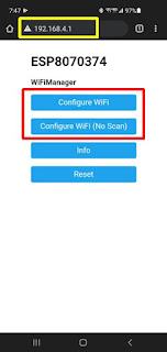
You can select Configure WiFi to have the controller scan for local WiFi networks (note this may take up to a minute to complete, so please be patient), or you can select Configure WiFi (No Scan) to skip the scan and manually enter your Wifi name.
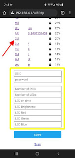
password: The password for your WiFi network
Number of PIRs: This will be either 1 or 2 depending on whether you plan on connecting and using one or two motion detectors. Two motion detectors might be used for something like stairs, where you want motion detected (and the lights to turn on) based on motion either at the top or bottom of the stairs.
Number of LEDs: Enter the total number of LED pixels in your installation, up to a max of 600. If you do not know the exact number at this point, just enter an approximation and you can come back and modify this (or any other setting) later.
LED on time: Enter the amount of time, in seconds, that you wish the lights to remain on after motion is no longer detected. The lights will automatically turn off after this time expires.
LED Brightness: Enter a value between 1-255 for the brightness of the LEDs. Again, this value can be changed later. Note that very low values (<10 or so) may not be visible.
LED Red, Green and Blue: Enter a value between 0-255 for each of these to determine the color of your lights when on. For example, to have blue light only, enter 0, 0, 255. For white, enter 255, 255, 255. If you need assistance, you can use an online color wheel, such as as this HTML Color Picker. Click on your desired color and note the RGB values. Enter these as the values for Red, Green and Blue respectively.

Once all values are entered (again, they can be updated later.. just assure all values are entered and within the appropriate ranges), hit the Save button. If all values are accepted and written to memory, the following will be displayed:

The controller will reboot and attempt to connect to your WiFi network. If successful, the ESPxxxxx wireless network will disappear and stay gone. If it fails, the ESPxxxxx network will reappear and you can try again. Once it is connected to your WiFi network, connect your device back to your normal Wifi and the board is ready for use. You will want to obtain and note the IP address of the controller on your network. This will be needed if you want to change the settings, reboot the controller or later perform over-the-air updates. You can likely find the IP address via your router, but the method will be dependent upon the router itself.
If you noted the MAC address when you flashed the software, you can use that to assist in locating the IP address. You can also use the hostname, which should be similar to the temporary access point that was created above. You are now ready to assemble the controller board.
Building the Controller
I'd highly recommend that your first build and test the controller board with temporary connections on a breadboard before making the permanent soldered version. You can use the same wiring diagram listed below to create the controller on a breadboard.
D1 Mini Controller Version
 |
| Click on picture to enlarge |
This version is nearly identical to the version I cover in my YouTube video Building your own LED controller. If you want see a step-by-step process of building the controller, please watch that video. There are just a few important differences that you should note:
- The software installed in that video is WLED. The software installed for this version is covered above, so you can skip the section on the WLED installation.
- There is an optional button installation. This version does not use a button, so you do want to omit that optional step.
- While WLED can be installed on either an ESP8266 or ESP32, this particular version can only be installed on the ESP8266 due to the libraries used in the custom firmware.
Next, the motion detector(s) need to be wired to the controller:
 |
| Click to enlarge |
Finally you are ready to install in the desired location and connect the controller to the power supply and LED strip.
 |
| Click to enlarge |
You should have the +5V lead, ground lead and LED data signal wire left from the control board that still need to be connected at this point. If built as described, these wires will come from the underneath side of the board as shown above. Connect the +5V lead to a the +5V lead from the LED strip and run both to the positive terminal of your 5V power supply. Repeat for the ground on both the controller and and LED strip. I show the use of Wago connectors here, but you can use wire nuts, solder the connections together or whatever method you prefer.
Finally the signal wire (shown in green above) needs to connect to the DIN (data in) of the LED strip. Again, I am using a spade and JST connectors here, but those are optional. Just assure your connections are at the data IN end of the LED strip (indicated as well by the arrows, which indicate the direction of the the data flow).
NodeMCU Controller Version
 |
| Click to enlarge |
The NodeMCU version, while being larger in size and had the two available power rails, is a bit easier to create as all connections can be made on the top side of the ElectroCookie board and can be done before or after the NodeMCU and logic level shifter are soldered to the board. Again, like the mini version, if you only need one motion detector, connect that one to the D5 pin on the NodeMCU.
 |
| Click to enlarge |
The NodeMCU version is connected to the 5V power supply and LED strip in the exact same manner as the D1 mini version. Again, just assure you are connecting to the "data in" side of the LED strip.
Power on process
Regardless of which controller you build, once all connections are verified, plug in the 5V power supply to AC power. A couple of pixels may light up when power is applied, but the strip should turn briefly blue, then turn off to let you know the boot process is complete. At this point, any motion detected by your motion sensors should turn on the lights in the color and for the duration you specified during setup.
Rebooting the controller, changing options and updating the software
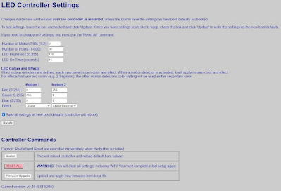
Starting with v0.30 of the firmware, a web interface is now available to change options and perform other commands like restarting or resetting the controller. You need to know the IP address of the controller for these options (see above on obtaining the IP address). Once you have the IP address, simply enter it in the browser of a device on the same WiFi network as the controller.
Modifying the Program
If you wish to make changes, such as increasing the maximum number of LEDs, changing the pins used, etc., the source is provided in the Github repository. More information can be found in the repository's wiki. If you do make improvements to the code, please feel free to post a pull request and I can consider adding it to the base application if there is enough interest.
Please let me know in the comments below if you have any questions!
Links
YouTube videos:
Other Links:
NodeMCU PyFlasher (for flashing firmware to your controller)
Supporting this blog and related YouTube channel
If you'd like to support future content on this blog and the related YouTube channel, or just say thanks for something that helped you out, you can use any of my Amazon links to make a purchase at absolutely no cost to you. Or if you prefer to say thanks directly, you can buy me a one-off cup of coffee at:
Could the D1 mini be used with the large prototype board? Would any changes to the wiring be required?
ReplyDeleteAbsolutely. In fact, it would make wiring a bit easier as you could use the power rails on both sides for the 5V and 3.3V to power the logic level shifter. Basically, you'd wire it just like the full NodeMCU version above, but just substitute the D1 Mini for the full size NodeMCU board. Just check your pin alignments and assure you are hooking up the right voltage to the right pins (for example, the 5V and 3.3V pins are generally 'reversed' and on opposite sides of the board between the full NodeMCU and D1 Mini.. be sure not to hook up 5V to the 3.3V pin!).
DeleteI think I followed correctly but I only had 1 led lit at the end is there something I missing
ReplyDeleteFirst, assure that you have defined the correct number of pixels for your setup in the web application. If you've done that and are still only getting a single pixel to light up, that generally refers to a problem with the signal from the controller to the LED strip. Double check your solder connections between the D1 mini (or NodeMCU) and the logic level shifter and the connection between the shifter and the start of your LED strip (and make sure the data in line and data out line are using the same "channel" on the shifter). A single pixel like that is almost always related to a missing or bad signal from the controller.
Deletecheck all pin connection even check for continuity same single single pixel.. I did increase the number of pixels to 150 on the web
ReplyDeleteit worked I left it plugged in a bit longer then the single pixle turned blue from green then I reset and bam its up an running
ReplyDeleteOutstanding! Congrats. Yes, I guess I should have mentioned that when first powered up, a single pixel may light up when power is first applied during the boot process. When the boot process is complete, the LED strip will flash blue for around 2 seconds to let you know that the boot process has completed successfully. In my case, this happens in just a few seconds, but in some situations it might take a bit longer to connect to the your wifi. If more than around a minute passes without the flashing blue lights, then that means something didn't boot properly (or something is wired wrong).
DeleteBut I'm glad you got it working. Let me know if you have any other questions or issues.
I am going to try to modify your piece of code to try to make this no automation work with the TOF sensors; since we have to connect 4 pins now to the sensors instead of three (SCL and SDA), I am assuming one would be the signal and the clock; how might you control those pins in the piece of code?
ReplyDeleteLet's say, I have connected D5 to SCL and D6 to SDA for DOWN sensor (and D1 and D2 for UP), and I have already defined those in the initialization of the code:
#define MOTIONUP_SCL D1
#define MOTIONUP_SDA D2
#define MOTIONDOWN_SCL D5
#define MOTIONDOWN_SDA D6
The piece of code I want to check is this one, since we are working with two sensors; I am assuming I need to remove the old MOTION_PIN_1 and MOTION_PIN_2 and replace it by the definitions I have just set at the beginning... so, do I have to put in the condition both "pins" as "high", like:
if (numPIRs > 1) {
if (digitalRead(MOTION_PIN_1) == HIGH) {
//replace previous line by this:
if (digitalRead(MOTIONDOWN_SCL) == HIGH) && (digitalRead(MOTIONDOWN_SDA) == HIGH) {
if (!lightsOn) {
toggleLights(true, 1);
#if defined(SERIAL_DEBUG) && (SERIAL_DEBUG == 1)
Serial.println("Motion DOWN Lights on");
#endif
}
onTime = millis();
} else if (digitalRead(MOTION_PIN_2) == HIGH) {
//replace previous line by this, for the other sensors
if (digitalRead(MOTIONUP_SCL) == HIGH) && (digitalRead(MOTIONUP_SDA) == HIGH) {
if (!lightsOn) {
toggleLights(true, 2);
#if defined(SERIAL_DEBUG) && (SERIAL_DEBUG == 1)
Serial.println("Motion UP Lights on");
#endif
}
onTime = millis();
} else if ((digitalRead(MOTIONDOWN_SCL) == LOW) && (digitalRead(MOTIONDOWN_SDA) == LOW) && (digitalRead(MOTIONUP_SCL) == LOW) && (digitalRead(MOTIONUP_SDA) == LOW) && (lightsOn) && ((millis() - onTime) > (ledOnTime * 1000))) {
toggleLights(false, 0);
#if defined(SERIAL_DEBUG) && (SERIAL_DEBUG == 1)
Serial.println("Lights off");
#endif
}
Thank you!
Unfortunately, it's quite a bit more complicated than that. The ToF sensors are I2C devices. While they can share the same pins on the ESP, each needs to have a unique I2C address. That means one of the devices needs to have its address changed... you can't have to I2C devices with the same address. You'll then need a library to communicate with the VL53L0X. The ToF sensors are reporting distance, not motion. The original version used ESPHome to report a binary "motion" when the measured distance was less than a set value. So, an Arduino library will be needed to 'talk' to the two sensors...each with their own address. You'll then need to compare the measured distance to whatever 'minimum' value you want to set to say that the 'beam had been broken'.
DeleteSimply defining pins as SDA and SCL will not 'communicate' with the ToF sensors. You will need to implement a library such as this: https://github.com/pololu/vl53l0x-arduino and change the code accordingly to use that library.
Hey Victor, did you managed to make it work? I was about to embark myself in this, but I'm super rusty on my coding skills
DeleteHello.
DeleteI finally went with the "complex" installation through Home Assistant and the distance sensor rather the motion ones... Have the system designed and done, but haven't had the chance to install it yet on my stairs, since I need to run a line to the point where I want the plugs to be so, that's probably a winter project :D
This comment has been removed by the author.
Deleteohh okay. I suppose I need to start derusting mi skills. Thanks!
DeleteThanks again for the interesting and helpful videos/blogs. On this version you are connecting both PIR sensors to the D1 Mini/I2C devices. If using the ToF sensors can you still wire both to the D1 Mini/I2C devices or do you need to put a D1 Mini with each ToF sensor?
ReplyDeleteBTW, for the +5/Gnd 'IN' connections to the D1, what gauge of wire are you using. I tried 18 gauge stranded and the holes on the Electro Cookie are a tad small to accommodate the 18 gauge.
While it is possible to use the ToF sensors, these are I2C devices. Each I2C device connected to the controller must have a unique address. This means you'd have to connect one of the ToF sensors to some sort of programmer and send the commands to change its address. In addition, the code would have to be modified with the appropriate libraries to "speak" to the ToF sensors and to determine the how to convert the measured distance to a "true/false" binary sensor. And in this case, using a separate controller for the ToF devices would then require some sort of automation system (like Home Assistant/NodeRed) so that the ToF controller could communicate with the LED controller. See my reply to the comment just prior to this one, which was asking the same thing.
DeleteAs far as wire gauge, it somewhat depends on the project, but I generally use 20 gauge wire for most of my ElectroCookie connections.
Thanks again for the prompt reply!
DeleteThanks for the project. I have been able to get it working with the exception of the solid effect. I am not any good at programming and seeing that chase for example works, am assuming that might be a coding issue. Any thoughts? Thanks.
ReplyDeleteI think you are correct. It's been a long time since I worked on this project but a quick glance at the .ino file on Github shows that the solid effect is not being processed as a function... even though the code compiles. This is likely due to a missing (or extra) bracket in one of the pre-processor directives. In other words, it likely is the code.
DeleteI will certainly put investigating fix on my list, but I have numerous other projects underway so I can't say exactly when that will be. I also have to dig out the test system (I'm using the Home Assistant version), assuming I can find it! But I will open an issue on this repo as a reminder. When that issue gets closed and/or a new version is released, I'll try to remember to follow up to this comment. Sorry the solid effect isn't currently working. I'll get to it as soon as I can.
OK... I built a new system (couldn't find my original) and confirmed that 'initially' the solid effect wasn't working. But can you try the following and let me know the results (here or in the Github issue... which I'll update with this same info)?
DeleteSelect an effect other than solid for both PIRs (if using two... otherwise just the one). Save this as the new boot defaults. After the controller reboots, check that your newly selected effect is working. Then try changing the effect to solid. In my case, this worked. I could then save the boot defaults with solid as the effect, and it continued to work. After this, I could freely switch to any effect (including solid) and it worked as expected.
I suspect something isn't getting written to the config correctly upon initial setup and when solid is the default. Changing the effect to something else and saving the config then allows the solid effect to be selected. Can you please let me know if this works for you as it will help me with troubleshooting on the code. Thanks!
I just wanted to follow up to let you know that I released an updated version of the firmware that fixes the issue you were experiencing. I fixed a few other things and introduced a number of new features as well. You can find the full release notes here: https://github.com/Resinchem/standalone-led-controller/releases/tag/v0.46
DeleteFirstly, I want to express my gratitude for sharing your project and all your hard work. I've successfully set it up, and it's performing admirably. I'm hopeful that in the future, you might consider upgrading it to utilize ToF instead of PIR sensor, as I lack the expertise to modify the code myself. Additionally, I was wondering if there's a possibility of updating the firmware to adjust the speed of the chasing effect. My staircase has two turns, and the current speed feels a bit sluggish. Once again, thank you for your contributions and for sharing your creations with us.
ReplyDeleteAdding the ability to use ToF sensors is on my long list of requests for enhancements for my various projects. I really would like to do it and I don't think it would be extremely difficult to do. What makes it a little harder is I would like to combine it with the same code that uses the PIR sensors so that I don't have to maintain two separate versions moving forward. So, it is on my list... I simply don't know when I will find time to write the code, test it and publish it.
DeleteAs far as the speed adjustment, that is a bit easier to accomplish. In fact, I should have added that from the start. I will add that the next time I make an update to the code... but again, I just don't know exactly when that might be.