These animatronic props have LED eyes that change color, a rotating head and optional sound that all activate via motion detection. Alternatively, on board motion can be disabled and all features controlled via automation (like Home Assistant) using MQTT.
I got the idea for this project from another YouTube video that used a Wyze cam and Raspberry Pi to track movement and for the rotating head to "follow" someone. Honestly, I tried this but got very inconsistent results. My goal was to have this in the driveway during trick-or-treat and I wanted consistent results. I also wanted color-controllable LED eyes and sound. So, I ditched the idea of a Pi and Wyze cam and moved to a NodeMCU and PIR motion detector.
My original goal was to just build one... but why build one when you can build two at twice the cost! Actually I ended up with two because I ordered two different masks and Styrofoam heads (see parts list below), as I didn't know what might work best. There are some slight differences between the assembly and code for these two and I'll note them below by referring to "skull head" (left in photo above) and "goblin head".
I also have a YouTube video showing the above two builds "in action" on Halloween night! In addition, the video provides an overview of the build and operation. It doesn't provide all the details on the build, especially the controller and component wiring, but you may wish to give it a watch to get an idea of the project before digging into the full details below.
Parts List
As always, I like to start with a parts list. In this case, there is ample room for substitution based on exactly what you want to build. For example, with the PVC frame, my "monsters" stand between 5' and 5 1/2' tall. Obviously, you can build a different frame... even using different material. Similarly, if you don't want a particular feature, such as sound, you can eliminate the DFPlayer, microSD card and speaker. This is just a list of what I used in my project.
Note this list is to build ONE monster.
*Links may be Amazon affiliate links. While this does not affect your pricing, this blog may earn a small commission if you make a purchase.
Frame Assembly
The frame is simple 1 1/4" PVC. I debated about the diameter to use. Moving up to 1 1/2" would have gave me more connection options (like a 5-way at the base for better front/back support), but would have made everything bulkier and heavier.
None of the parts are glued together. The goal is to disassemble and store between Halloweens and easily pull out and reassemble the next year. This is also why Dupont connectors are used (see wiring below).
But due the lack of glue (no matter how hard I pushed the joints together, the assembly is a little top heavy when the head is installed and it can tend to move forward/back if pushed or bumped.
And I found this out the hard way. Halloween this year came with 20+ mph wind gusts and both props took face plants (see the YouTube video to watch it happen)! Next year I'll find a better way! I'd recommend using a 5-way furniture PVC like this:
That way, support could be added to the front and back to prevent what happened to me!
One other item of note are the elbows at the "shoulders" of the frame. This wasn't done for appearance, but the zip tie the cloak to create slack in the hood for the rotating head. More about this in the cloak installation section.
Servo Mounting
This was one of the more challenging parts... and took some trial and error. First, I needed a stationary base that would not rotate on which to mount the servo. Then I needed to mount this assembly to the PVC frame, again assuring no rotation.
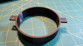
This is where the first 3D printed part comes into play. I designed and printed a cap for the top section of PVC that tightly fit over the PVC and would not rotate. In the center of this cap was a square hole that would receive the down rod from the servo mounting platform.
For a little extra security, a little hot glue was used between the top of the cap and the underside of the servo platform. But this also meant that the servo needed to be a little more off-center to clear the 3D printed cap. This also contributed to some additional balance problems I'll get to in the head assembly and mounting section.
For the servo, a combination of a drill and palm router was used to create the hole and the servo was screwed to the base with a couple small screws.
The completed base can then be inserted into (and easily removed for storage) from the PVC frame.
Head Assembly and Mounting
This was the next challenge. I needed a platform for the head and a way to mount this platform to the servo while allowing free rotation. After cutting a square platform out of the same hobby wood as the servo mount, I drove 4 small 1 1/2" nails from the underside to act as "spikes" for pushing into the base of the Styrofoam head. Eventually, I'd come back and add some hot glue around the base of the Styrofoam head, but I wanted the head to be removable during assembly and testing.
Next, I had to find a way to mount this on the servo. I selected the largest horn that came with the servo and used a couple of very small brads to nail this to the exact center of the underside of the platform.
While this allowed me to mount the platform to the servo, it was extremely unstable. Even with just the Styrofoam head alone (without the weight of the mask), the head platform would simply tumble off the mount when rotating. Enter the next 3D printed part.
It took a few tries to get this part just right, but it about 1/2 mm shorter than the gap between the head platform and servo platform. This allows free rotation, but stops any wobble that would cause the head platform to tumble off. This ring was simply screwed to the underside of the head platform.
Because the ring will be sliding over the servo platform, the top of the servo platform should be a smooth as possible (sand if necessary) and the screw that mounts the servo platform to the mounting rod should be flush, or slightly countersunk. When assembled, the ring should just be touching or slightly above the servo platform.
Counterbalancing for face masks
One final caveat... while the above system works flawlessly for "skull head" (see top photo to indicate which mask I'm referring to) since it is a full head mask and pulls over the head.
This is pretty well balanced, weight-wise, when installed on the Styrofoam head. However, "goblin head" is just a face mask, with the elastic band that would normally go around the back of the head.
When installed, this made the head extremely front heavy. So much so, that even with the balancing ring installed, the head would still occasionally tumble off the servo mount when rapidly moving. For this reason, and after a lot of trial and error, I had to install a counterbalance on the backside of the Styrofoam head (in this case a metal bracket and large screw into the Styrofoam).
Once counterbalanced, the head no longer tumbles off the mount, but I'd recommend selecting full head masks to avoid this problem in your own build.
LED Eyes
Once your have your masks placed on the Styrofoam head, balanced and in the desired position, use a Sharpie or other marker to note the position on the head where you want the LED eyes to be mounted. Note that due to the small size of the Styrofoam head, this may not be in the center position of the Styrofoam eyes.
Remove the mask and use an X-ACTO knife or similar to carve out a small hole and channel to mount the LEDs. You want to try to get the LEDs in a position so that the very top of the LED is pointing straightforward for the best effect. Separate the LED leads slightly to connect Dupont connectors and hot glue into place. When the glue is set, connect your Dupont leads (or solder and heat shrink if desired) and run along the sides of the head to the bottom rear of the neck, where they will eventually connect to the controller leads.
I'd recommend applying a little hot glue to the connection between the Dupont connectors and LED leads and to secure your wiring to the head with some small wire clips pushed into the Styrofoam and/or a little hot glue.
With this complete, you can set the head aside. Once finally assembly and testing is complete, you may wish to use a couple of straight pins pushed through the rubber of the mask and into the Styrofoam head to prevent the head from slipping inside the mask during rotation and moving your LEDs out of the proper eye position.
Controller and Wiring - 2 options
Up until this point, both versions of the build have been the same (except for the counterbalance for "goblin head"). But here's where they are going to diverge slightly. First, let's cover the features that are the same between both:
- Will react to motion, light up (or change color) of the LED eyes, rotate the head and play an audio file. Eyes can be made to blink at a random interval when idle (no motion). Eye colors, direction of head rotation and speed are all customizable.
- Both have the option to disable the auto-motion and control via automation using MQTT for eyes, head rotation and audio.
But here's where they diverge:
"Goblin head" has the ability to control each eye independently... each eye can be a different color and individual eyes can blink. This comes at a sacrifice of the Arduino serial monitor... which generally won't be used after final testing as the NodeMCU will be wireless.
"Skull head" only has control of both eyes as a single entity. Both eyes will always be the same color and will blink together, but it preserves the ability to use the serial monitor. This option also takes just a little more wiring on the board as well.
I'll cover both here and you can decide which one you prefer (or like I did, use a different one on two different monsters!). Of course, you could also mix and match. Besides control board wiring, there are also some difference in the code sets, but that will be covered below.
Bench Testing
While completely optional, I personally like to do a bench test using just an ordinary breadboard, jumpers and Dupont cables before I create a final soldered version. This also allows me to easily remove the NodeMCU and flash different versions or options to the firmware to try out different options via USB if I don't have over-the-air (OTA) updates enabled yet. You can follow the same instructions, using the same row/column numbers as the soldered version and just connect to free-standing LEDs, servo, motion detector and speakers for the bench test.
But if you do this, and want to test the servo, remember that the servo will need powered directly from the 5V power supply and not the NodeMCU. If you also have the NodeMCU connected to the power rail on the breadboard, be sure to disconnect the USB cable before powering up. NEVER connect both a 5V source and the USB cable to the NodeMCU at the same time... or plan on kissing your board goodbye!
Once you have everything working as desired, you can create the final soldered version.
Regardless if you do a bench test or not, I highly recommend installing the initial Arduino code to the NodeMCU before controller assembly as the first load requires a USB connection to your computer. Once you have the initial load and over-the-air (OTA) updates working, you will no longer need to use a USB connections to make changes or upload new versions of the firmware and can proceed with creating a soldered version.
Common wiring:
There are a few things that will be applicable to both versions. I'll cover them here to avoid having to repeat under each variation.
Cable Management
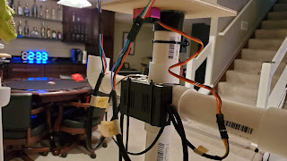
When you are done with the controller you will have between no less than 18 wiring leads extending out from the board. Add in any jumpers or extensions and you can end up with quite the wiring mess. I like to run my related wires inside some braided wire sleeve to keep things organized, sealing the end with heat shrink tubing.
 |
| A partially completed controller using braided sleeve for wire management |
While this is entirely optional, I just mention it because if you opt to do this, remember that you MUST install the sleeve before attaching any connectors (like Dupont or spade) to the lead. I find 1/4" sleeve works pretty well for 2-wire and some 3-wire smaller gauge runs and 3/8" works for 4-wire or 3-wire larger gauge runs. I would recommend labeling your wiring regardless, so as not to confuse left LED with right LED or worse yet, the PIR motion sensor wiring with the servo wiring!
Ok... on to the controller build:
First and foremost, before installing anything on the ElectroCookie board, solder jumpers at the end of each board to connect the two power rails together.
Next, in both versions, the NodeMCU and DFPlayer Mini audio board will be installed in the same place. I'll be using the row and column numbers of the ElectroCookie board as a reference, so if you do not install the controllers in the same location, you will need to adjust the instructions accordingly.
The NodeMCU first pins (VIN and 3V3) should be installed in the first column of pins (column 1) of the ElectroCookie board, with one row of pins available on the top and the bottom. For the DFPlayer Mini, the first row of inner pins should be installed in column 23 of the ElectroCookie board (meaning the last row of pins should be in the final column, 30). This is one row narrower than the NodeMCU, so I recommend that the extra row of pin holes be exposed on the bottom since all connections will be on this side of the board. This means the bottom row of pins should be placed in row C. Be sure to orient this board properly... the 'DFPlayer Mini' label should be facing in and the opening to insert the microSD card should be facing out. This means the VCC pin should be in the lower left corner as shown in the diagram above. Here's a pinout of the DFPlayer Mini as an additional reference:
General internal wiring (on board point-to-point):
For internal 'on board' connections... these are connections that bridge from one point of the board to another. I like to use 20 gauge solid wire for these as it is easier to bend, route and keep in place than stranded wiring.
General external wiring (board to components):
When making your connections between the board and external components, you will probably want a way to 'disconnect' these when it comes time to disassemble and store your build for the next holiday season. There are many ways to accomplish this... Dupont cables, spade connectors, Wago connectors or even wire nuts. And while some wire runs will be short (e.g. servo and speaker), others will be much longer... like 5' for the motion detector. Also remember than when connecting to the LEDs on the head, you need to assure there is enough slack to allow the head to rotate without pulling on the wires. So feel free to use whatever connection method you prefer, but here's my general approach:
I start with a standard Dupont cable that is female on one end and cut off the other end, strip and solder to the board. On the component end, I use another standard Dupont cable that is female on one end and either male or female on the other depending on the connection to the component. In between I create a custom male-to-male jumper wire, cut to the length I need. I use 22 or 24 gauge stranded wire for all custom wiring that connects from the board to an external component or for my jumpers.
Goblin Head Control Board Wiring
(Independent eye control - no serial monitor)
 |
| Click on diagram to see enlarged version |
I know... this looks really convoluted at first glance. But don't worry, I'm going to cover all the connections here, following the steps outlined above that are common to both versions.
Internal on-board connections
We'll start by making all the internal 'on board' connections. First, connect the VIN pin of the NodeMCU to the positive power rail (J1→5V+). Don't make this connection to the first column of the power rail, as we'll need that for the incoming 5V power supply. Next connect the GND of the NodeMCU to the negative, or ground, rail (J2→-5V).
Next, connect the power to the DFPlayer Mini. Connect VCC (A23) to the +5V rail on the opposite side from the NodeMCU connection. Then connect GND (A29) to the -5V rail.
Now, we'll make the connections between the NodeMCU and the DFPlayer. Connect the RX pin of the NodeMCU to the TX pin of the DFPlayer and the TX pin of the NodeMCU to the RX pin of the DFPlayer:
NodeMCU RX (A4) → DFPlayer TX (A25)
NodeMCU TX (A3) → DFPlayer RX (A24)
Be sure to route these wires so as not to block the "A" column of other pins on the NodeMCU, as we need to make connections here later.
External component wiring
Let's start with the LEDs... as each LED requires 4 connections back to our board... one to ground and the other 3 to separate pins on the NodeMCU.
For reference, here's a diagram of a common cathode RGB LED. The longer lead is the connection to ground. The single lead on one side of the common is the red lead, with green and blue on the other side, in that order.
For the left LED (left eye) of the Goblin head, connect the R(ed) lead to the D1 pin on the NodeMCU (A14 on the board). Connect (-) lead to the ground rail on either side of the board. Connect the G(reen) lead to NodeMCU D2 (A13) and the B(lue) lead to D3 (A12). Remember to use some kind of connector between the board and the LED so that they can be disconnected... and to leave enough slack in the wire to allow the head to rotate without pulling on the wire. Summarizing:
LED Lead → NodeMCU Pin / (ElectroCookie Board)
R D1 (A14)
(-) --- (ground)
G D2 (A13)
B D3 (A12)
Now repeat for the right LED (right eye), using the following connections:
LED Lead → NodeMCU Pin / (ElectroCookie Board)
R D6 (A7)
(-) --- (ground)
G D7 (A6)
B D8 (A5)
Servo
Next, wire up the servo. For the 5V and ground, just wire to any (+) and (-) on the power rail. Just be careful not to reverse the polarity. Servo wiring comes in a couple of different color schemes... check your servo documentation. Finally, connect the servo data line to the NodeMCU D4 pin (A11).
Servo → NodeMCU Pin / (ElectroCookie Board)
(+) --- (+) rail
(-) --- (-) rail
signal D4 (A11)
PIR Motion DetectorThis is similar to the servo, except that the PIR sensor will be powered off the NodeMCU 3.3V pin (A1) instead of the +5V rail. The data line will connect to the NodeMCU D5 pin (A8) and GND to the (-) rail.
PIR Motion → NodeMCU Pin / (ElectroCookie Board)
(+) 3V3 (A1)
OUT D5 (A8)
(-) --- (-) rail
Speaker
This one is easy.... just run two connections from the DFPlayer speaker pins (B28 and B30) to the two speaker leads. It doesn't matter which lead connects to which pin. They are interchangeable.
5V Power Supply
Finally, connect a positive and negative lead from the first column on the top power rail. These will connect to the (+) and (-) of the 5V power supply. Again, just a reminder... do not connect the board to both the 5V power supply and USB power on the NodeMCU at the same time!
That's it for this version of the controller. Now let's look at the Skull head option.
Skull Head Control Board Wiring
(Joined eye control - serial monitor available)
While similar to the Goblin head board, this version does not use the NodeMCU RX/TX pins so that the serial monitor is still available. However, to do this, it requires that both LEDs (eyes) are driven off single R-G-B pins, using only 3 pins instead of the Goblin head's 6 pins (two grounds are also required in both cases, but there are plenty of ground connections available on our two power rails). We will use a couple of these vacated pins for the RX/TX of the DFPlayer. Otherwise, the remaining wiring remains the same between both versions.
Using the same NodeMCU pins for RGB that we used for the right eye/LED of the Goblin head - D6, D7 and D8 for RGB respectively. But instead of running from these pins to the LED leads directly, we are going to run each to an unused column of the ElectroCookie board between the NodeMCU and the DFPlayer. We can then connect the appropriate lead for both LEDs to this same column... in effect powering both from the same NodeMCU pin.
Here's the columns and rows I used:
NodeMCU Pin / ElectroCookie → ElecroCookie Column → LED Lead (both)
D6 (A7) (B21) R (D21 & E21)
--- (-) rail --- (-)
D7 (A6) (B20) G (D20 & E20)
D8 (A5) (B19) B (D19 & D20)
Servo
The servo is also very similar to Goblin head, except we are going to use NodeMCU's D1 and D2 pins for RX/TX instead of the boards RX/TX pins. Like the Goblin head, connect the VCC and GND of the DFPlayer to the (+) and (-) rails of the ElectroCookie. Then NodeMCU D1 pin (A14) to the TX pin of the DFPlayer (B25) and the D2 pin (A13) to the RX pin of the DFPlayer (B24).
Remaining Components
The remaining components... servo, PIR motion, speaker and 5V power supply are identical to the Goblin head. Refer to those connections above for details and to complete this version of the controller.
DFPlayer Mini Prep
You will need to copy any desired .MP3 audio files to a microSD card (formatted as either FAT16 or FAT32), but the order that files are copied is important. All files should be copied to the root directory of the microSD card. The first file copied is considered "track 1", the second file "track 2", etc. regardless of the file names. The Arduino code will always play the first "track" (the first file copied to the card), so be sure this is the first file you copy to the card. If you copy over additional files, they will be playable via MQTT commands (if you enable that option), but the code always plays the first track.
Simply copy your desired audio file(s) from your PC to the root of the microSD. Note: if you are using a Mac to copy files, additional steps are needed as Macs create a hidden file upon copying of an .mp3. See the link below for more details
You likely will want to use short "Halloween" sounds like an evil laugh or moan, but note this is not required. There are a lot of great free .mp3 Halloween sounds available for download. Just Google it! You could alternatively play an actual song or any other valid .mp3 file.
Component Mounting
Regardless of which controller you opt to build, the dimensions of the board are the same, so I place mine into a 3D printed enclosure and just zip tied it to the rear of the PVC 4-way connection just below the head.
The speaker that I used already had small "tabs" with holes for mounting. I drilled out these holes a bit to make them large enough to pass a zip tie and mounted this on the front, just under the head when in center position.
I toyed with the idea of trying to mount it to the moving head platform itself so that it appeared the sound was coming from the mouth regardless of which direction the head was pointed, but I was concerned about the wire runs with the rotating head, so I opted for a stationary position. To be honest, from behind the cloak, you really can't tell.
I also placed the PIR motion sensor in a 3D printed enclosure with "fins" to limit the width of motion detection to assure the routine didn't fire until someone was closer to the optimum position (the default sensor angle is 100°).
If you don't have a 3D printer or wish to even further limit the angle range, I've found that using an empty toilet paper tube placed over the PIR sensor allows pretty accurate control of a very narrow detection range.
Regardless, the motion detector can't be hidden behind the cloak! I opted to mount mine on the bottom crossbar of the PVC frame. I used an angle bracket and screwed it in at a slight angle so that it points up. It is also adjustable to the left/right using this method and I can easily move it to the opposite side if needed on Halloween night!
Finally, I ran 5V power leads from my controller to the base of the frame so that it could easily be unplugged/plugged in from behind the frame without needing to fumble around inside the cloak.
I used Wago connectors and 20 gauge wiring to also make disassembly and storage easier.
Cloak Installation
Before installing the cloak, I'd highly recommend that you complete all other assembly, mounting, testing and tweaking your code... including finding the center position of the servo before attaching the head to the mount. This is because I found that I needed to bind the "shoulder" areas of the cloak to assure the hood had freedom to turn with the head and not 'hang' from the head.
Then buttoning up the front to look decent required a number of safety pins and substantial 'fidgeting'. Reaching through the cloak to grab the vertical support to pick up and move the frame is doable... but any other work requires undoing the cloak to get to the wiring/components... and it never seems to go back the same way twice!
Arduino Code
I'm not going to go in-depth regarding the Arduino code here, as full documentation is available in my Github repo where full versions of the code can also be found. I'll just make a few notes.
First, there are TWO versions of the code depending upon which controller you built. They are not interchangeable, so be sure to download the version that matches your controller build (Skull head or Goblin head).
Nearly everything can be configured via the Credentials file (your wifi and optional MQTT login info) and the Settings file. The Settings.h file allows you to define default eye colors, enable/disable motion-activated mode, set a eye blink range, set the audio volume and more. You should not have to edit the main .ino file unless you want to change how the program works or built your controller differently than either of the two options given here. See the Github wiki for full details on the options in the Credentials and Settings files.
One other item of note... when the program first boots, it will auto-center the head position to the midpoint.... the 90° position if using a 180° servo... allowing the head to turn a full 90° in either direction. I'd recommend booting the program for the very first time without the head assembly attached to the servo. This way you can attach the head with the servo in the mid position and assure the head is pointed precisely forward (unless you truly do want the head offset). It will also auto-play the first audio track if present to let you know that boot has completed.
MQTT Control
It is entirely possible to disable the auto-motion activated features in the Settings and control the system via automation, using MQTT, with something like Home Assistant. For example, maybe you want the activation to occur when a door opens or based on some other sensor value or event. MQTT options give you complete control, including eye colors(s), blinking, head movement and position and playing of audio files (including tracks other than the first track).
While MQTT and auto-motion activations can be used together, just remember that anything you set in MQTT (eye color, head position, etc.) will be overridden by the program the next time motion is detected. You will normally want to use auto-motion activation or MQTT independently of each other.
3D Printed Parts
Finally, I've included .stl files of all the 3D printed parts I used in this project. Feel free to use, adopt or modify as you see fit for your project.
Halloween Already Over?
Hey... no problem!
Just change out outfits, update the sound effects on the microSD card (Ho, ho ho... or even a Christmas song... remember, any MP3 will work) and you have your effect for the next holiday season!
Links
Here are the links mentioned above, summarized in one convenient list!
Github repo with the code, setup instructions and 3D printed .stl files DFRobot wiki for more info on the DFPlayer mini (including special note for Mac users).
Supporting this blog and related YouTube channel
If you'd like to support future content on this blog and the related YouTube channel, or just say thanks for something that helped you out, you can use any of my Amazon links to make a purchase at absolutely no cost to you. Or if you prefer to say thanks directly, you can buy me a one-off cup of coffee at:


If we are not using this with Home Assistant do we need to configure the MQTT in the settings.h file?
ReplyDeleteNo. As stated in the repo and its wiki, MQTT is optional and not required. To disable MQTT, set the MQTTMODE to 0 in the settings.h. Then you can just leave the default values for the remaining three MQTT values (as they won't be used). Similarly, if you've disabled MQTT, you can also leave the four MQTT values in the Credentials.h file as the defaults (or substitute any dummy values you want... they won't be used anyway). I'd recommend that you leave the #define statements there, but if you set the MQTTMODE to zero all the other values should simply be ignored.
Delete