Need a higher tech, but inexpensive solution DIY solution to assist with parking in a consistent location? This project uses a low-cost ESP8266 or ESP32 and a strip of WS2812b LED pixels to replace that old tennis ball on a string you have hanging from the ceiling now! And if you have Home Assistant or another automation system, you can optionally enable MQTT to use the system as a vehicle presence system.
Spring 2025 Update: A major update to the firmware was released as version 0.50. This second YouTube update video covers these major changes, including support for the ESP32 and optional lateral guidance. These changes are integrated into the original article below.
Summer 2025 Update: Beginning with firmware release v0.52, the ESP8266 is unfortunately no longer supported. Due to continued addition of new features, it simply isn't possible to get the firmware to run acceptably on an ESP8266. If you wish to use an ESP8266, then you must install version 0.51 or earlier.
For all new builds, an ESP32 is now highly recommended as no new fixes/features will be added for the ESP8266!
Background Info and Prior Version
Way back in 2019, one of the first DIY projects I did was to create an LED parking assistant for my wife. Her side of the garage isn't very deep and there is little room at the front and back of the car when parked in the proper position.
This original system used a Raspberry Pi and a rather costly (~$70) LED matrix panel. It involved a lot of wiring, two power supplies and some tricky Python setup. But it has worked well and is still in operation today. And while this was originally build prior to the time I was using MQTT with Home Assistant, I'd eventually go back and add MQTT. But the system was not easy to setup and configure. Changing settings or options required editing the Python code. If you are interested in this older version, you can watch a YouTube video or read the related blog article.
But with what I've learned since about ESP controllers and LED strips, and the fact that at the time of this article, Raspberry Pis are extremely hard to come by... and very expensive if you do, I decided to see if I could create a lower-cost, easier-to-build (and use), version. The remainder of this article covers the build, configuration and use of this new system.
The New System
The new system uses LED pixels and different end-user configurable colors to create a 'countdown' to the proper parked position. It will flash if the car is pulled too far forward, indicating the driver should backup. Multiple 'countdown' effects can be selected and all distances for different "approach zones", from a minimum of 12 inches up to 16 feet can be entered via a simple web interface. More on this below.
If you prefer to watch instead of read, you can see a YouTube video of the system, but this article will contain additional information, such as parts lists, wiring diagrams, etc. So, you may want to watch the video for an overview and then return to this article for more specific build details.
Parts List
As usual, I like to start with the parts list required for the project. Note that if you've done other LED projects in the past, you may already have a number of these parts. In fact, I built the entire system from spare parts I already had and didn't need to purchase a single item... but your mileage may vary! Some items may be optional or substituted (others cannot), and I'll try to note that in the list or the build information that follows. These are the actual parts I used.
Some of these links may be Amazon affiliate links. Use of these links will not affect your pricing, but this blog may earn a small commission if you make a purchase. Use of these Amazon links is one the best ways to show your support for the blog and related YouTube channel... at absolutely no cost to you!
For the original ESP8266 version, the system has been tested with a Wemos D1 Mini, and although any ESP8266 dev board (like a NodeMCU) should work, there are currently some incompatibilities with certain other ESP8266 boards. If using an ESP8266, a D1 Mini (v3) is highly recommended at this point.
The current firmware version is not compatible with the newer D1 Mini v4 boards with the smaller ESP8266EX chip (and many have USB-C) due to issues with the UART/serial bus. See this issue in the Github wiki and assure you purchase a compatible board. For best (and most tested) ESP8266 compatibility, use a dev board with an ESP8266MOD chip.
For the ESP32 version, I opted to use an ESP32 Mini. But like the original, any standard ESP32 dev board should work. Note that other ESP32 series, like the "S-Series" or "C-Series" have not been tested and may require recompilation (and possible modification) to the source code.
Whatever board is used, it must have at least 4MB of flash. The older versions that only have 1MB or 2MB will not be able to accommodate the firmware.
Unfortunately, many of these parts only come in packs and not individually. That means if you have to buy parts, you'll likely have to purchase more than you need for this project. But the good news is that you'll have plenty left over parts for future LED projects!
Obviously, you also will need standard DIY electronics tools and supplies, such as solder, soldering iron, heat shrink tubing, etc.
Can I use a cheaper distance sensor?
If you've glanced at the parts list above, you probably noticed that the TFMini-s LIDAR sensor is easily the most expensive part, currently going for around $40. So, before beginning the project, I decided to test the TFMini-s against a couple of lower cost options to see if the additional cost was really necessary. I opted to compare the TFMini-s against two other distance sensors I has used on other projects, the ~$3 HC-SR04 ultrasonic sensor and the ~$6 VL53L0X time-of-flight sensor.
To test these sensors, I connected all three to a single ESP32 with some simple Arduino code that would take a measurement from all three sensors once per second for 3 minutes. I actually set this up in my garage and use my car to test accuracy, range and more importantly the precision or stability (noise level) of each signal at 1, 5, 10 and 15 feet. If you don't care about the test results and just want to take my word for it that (spoiler alert!) the TFMini-s is the best sensor for this project, feel free to just skip over the rest of this section!
But before I get to the actual test results, let's look at a few key specifications for each sensor.
HC-SR04 Utrasonic Sensor
- Working Voltage: DC 5V
- Working Current: 15mA
- Max Range: 4m (~13.1 feet)
- Min Range: 2cm (~0.78 inches)
- Measuring Angle: 15 degree
- Interface: Pulse/Echo (two GPIO pins)
- Approx Cost: $3
VL53L0X ToF Sensor (v2 breakout board)
- Working Voltage: DC 2.6 - 5.5V
- Working Current: 40mA (peak)
- Max Range: 1.2m* (~3.9 feet)
- Min Range: 50mm* (~2 inches)
- Measuring Angle: 25 degree
- Interface: I2C (two GPIO pins)
- Approx Cost: $6
TFMini-s LIDAR Sensor
- Working Voltage: DC 5V
- Working Current: 140mA (avg.)
- Max Range: 6m* (19.7 feet)*
- Min Range: 30cm* (11.8 inches)*
- Measuring Angle: 2 degree
- Interface: UART or I2C (two GPIO pins)
- Approx Cost: $40
*Both the VL53L0X and TFMini have programmable settings to adjust range and accuracy. For example, the TFMini-s reports a true range of up to 12m, but at a substantial reduced accuracy beyond 6m. For the purposes of this test, all devices will be used at default, out-of-box settings, which are listed above.
Test Results
A few notes about the testing itself. First, accuracy is somewhat relative here. Both because it was impossible to get the actual 'sensor' precisely aligned on the breadboard. In addition, due to the curvature of the front bumper of the car there is some slight differences in distance from the sensors to the actual car. What I'm really looking for here, though, is the range and "stability" of the measurements... in other words, does the signal bounce around or does it remain steady at various distances. All measurements were taken in millimeters.
1 Foot
At one foot, all three sensors reported 'in-range' readings.
 |
| Click chart for larger view |
Sensor | Min mm | Max mm | Avg mm (inches) | Variance (inches) |
HR-SC04 | 308 | 312 | 309 (12.2”) | 4 mm (0.2”) |
VL53L0X | 323 | 332 | 327 (12.9”) | 9 mm (0.4”) |
TFMini-s | 300 | 300 | 300 (11.8”) | 0 mm (0.0”) |
All three sensors performed OK at this distance, although the VL53L0X had the most 'bounce' varying by close to a 1/2", while the TFMini-s showed a solid, consistent signal throughout the entire test.
5-feet
Five feet was already beyond the maximum range of the VL53L0X.
 |
| Click chart for larger view |
Sensor | Min mm | Max mm | Avg mm (feet) | Variance (inches) |
HR-SC04 | 1537 | 1568 | 1549 (5’1”) | 31 mm (1.2”) |
VL53L0X | -- | -- | -- | -- |
TFMini-s | 1510 | 1520 | 1519 (4’10”) | 10 mm (0.4”) |
The HR-SC04 is a little bit noisier at this distance, but the total variance between the minimum and maximum reading was still only around 1.2". The TFMini-s did have a slight bit of noise as well, but it only had a max variance of 0.4". Both are still contenders at this point.
10-feet
 |
| Click chart for larger view |
Sensor | Min mm | Max mm | Avg mm (feet) | Variance (inches) |
HR-SC04 | 2995 | 3035 | 3015 (9’11”) | 40 mm (1.6”) |
VL53L0X | -- | -- | -- | -- |
TFMini-s | 3040 | 3050 | 3049 (10’1”) | 10 mm (0.4”) |
The results are about the same at 10 feet. There is a slight increase in the variance for the HR-SC04, while the TFMini-s variance remained the same. Interestingly, the TFMini-s reported a slightly higher distance at this range, while it has been slightly lower at the shorter distances. But this could be due to the fact that the angle of the car is slightly different. And the true distance using the tape measure is just an approximation anyway. At this point, both sensors have acceptable accuracy.
15-feet
15 feet puts the car just inside the entrance to the garage and where I'd want the parking system to "activate" and wake up. Unfortunately, 15 feet is also beyond the range of the HR-SC04, so I can only show the results for the TFMini-s.
 |
| Click chart for larger view |
Sensor | Min mm | Max mm | Avg mm (feet) | Variance (inches) |
HR-SC04 | --- | --- | --- | --- |
VL53L0X | -- | -- | -- | -- |
TFMini-s | 4640 | 4670 | 4650 (15’3”) | 30 mm (1.2”) |
The TFMini-s is showing just a little bit more noise at this distance, but the variance is still only about the same variance the HR-SC04 showed at only 5 feet.
Testing Conclusions
Due to both the longer range and the steadier signal, especially at the shortest range (where the parked distance is most critical, especially in my case where there is very little room for variance), I decided that the TFMini-s was worth the extra cost for this project.
The HR-SC04 might work if you have a little more leeway in the final parked position for your car and don't mind the system not waking and providing feedback until you are only 10-12' from the final parked position. However, the code I am providing is designed for the TFMini-s. If you want to use a different sensor like the HC-SR04, you will have to modify the code yourself to remove the TFMini and add the appropriate library for the HC-SR04.
LED Strips and Number of Pixels
There is one final consideration before getting into the actual build of the controller board and that is the size of the LED strip and the number of pixels. A longer display with more pixels means greater "sensitivity" (shorter distance change related to pixels lit) but also means a bigger power supply with higher current requirements. If the current requirements get too high (over about 2 amps), then a separate power run and more wiring will be needed (more on this below). There is also the consideration of number of pixels per meter. WS2812b pixels strips come in a variety of 'densities', such as 30 pixels per meter, 60/m, 100/m, 144/m, etc. Using the higher densities, such as 100/m or 144/m would permit more pixels in a shorter length, but it could result in a hard time for the driver to differentiate the various pixels, especially if a diffuser is used (recommended).
On the flip side, if you have the space for a lengthier display, you could use 30 pixels per meter, which gives greater separation between pixels.
Regardless of the density of pixels selected, I recommend a total number of pixels somewhere between 24 and 40. Anything less than 24 and there will be too little 'resolution' or 'sensitivity' especially when using effects where the distance is shown by moving from the outside edges to the center or from the center to the outside (effectively cutting the number of pixels in half from a sensitivity standpoint). Anything greater than about 40 will require a separate power run from the power supply directly to the LED strip and not through the controller board.
While technically not required, the effects will work better if you have an even instead of an odd number of pixels. For example, choose 30 or 32 instead of 31 pixels if possible.
For my build, I opted for 36 pixels at 60 pixels/m. This gives me a display length of about 2 feet, which will fit nicely in the planned installation location yet provide adequate resolution and sensitivity.
The code, as provided, has a hard limit of 100 pixels maximum. This is due to limitations of the ESP8266.
Building the Controller
If you've seen any of my other LED-related videos, this controller is very similar to the ones that I use for WLED. But I'll cover the basics, along with some of the key differences between this controller and the WLED version.
ESP8266 Version (no longer recommended)
 |
| Click to enlarge |
ESP32 Version
 |
| Click to enlarge |
The above diagrams shows the final wiring for the completed project, but first I'll focus on the controller board itself. I'm using "Mini" versions of the ESP. If you opt for a different dev board just adapt the above wiring to connect to the same GPIO pins wherever they are located on your board. If you use different GPIO pins, it will require that you modify the source code and compile your own firmware.
Also note that when using the ESP32, I utilize pin headers for mounting the ESP:
This is to accommodate the fact that most ESP32 boards are just slightly too wide to fit on a standard breadboard or ElectroCookie board and leave through-holes on both sides for wiring connections to the GPIO pins (there are some 'narrow' or breadboard friendly ESP32 dev boards as well - but they use non-standard GPIO pin locations). By using pin headers, you can make use of the through-holes under the ESP board for connections. In my case, since the ESP8266 and ESP32 minis have the same pin alignment, I could create a 'swappable' system where I could use the same base board for both ESP8266 and ESP32 testing. See the update video if you want more info on this.
I usually test everything on a breadboard first, and I recommend you do the same, before creating the permanent soldered version.
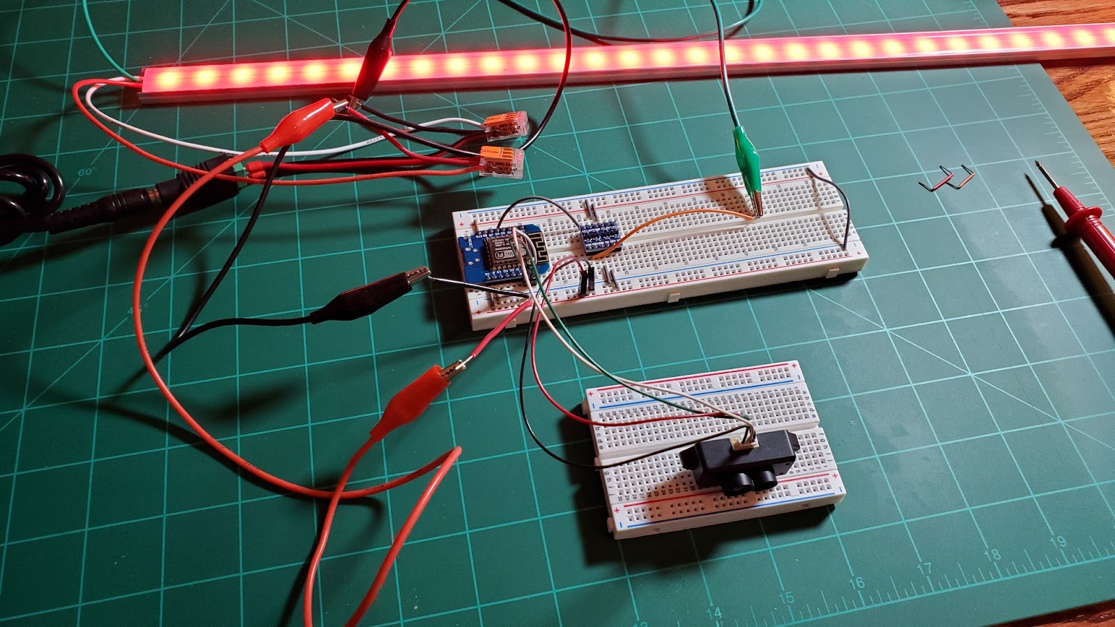 |
| Testing components and connections on a breadboard |
But since the ElectroCookie prototype board is basically laid out just like a standard breadboard, the connections are the same for both versions (the only exception is the power for the LEDs, but I'll cover that in a bit.
First, connect the ground rails on both sides of the board together. On the ElectroCookie board, there is a small gap that can be jumpered with wire or a solder bridge (circled in orange in the wiring diagram). We need a ground connection on both side.
Do not connect the positive rails... just the ground! We will be running 5V on one side (bottom in diagram) and 3.3V on the other for the positive rail, so assure you are only joining the negative or ground rails.
You can make connections and solder on the components in any particular order that works best for you and your soldering skills, but I'll present them here in the order I used. I'll also reference the row letters and column numbers from the ElectroCookie board in the above diagram. Note that the following are for the ESP "Mini" boards that I used. If using a different board type, you will need to adapt the following connections to match the power and GPIO pins for your board.
For example, most 'NodeMCU'-style boards have the location of the 5V pin and 3.3V pin in the opposite location than the 'Mini' boards. In this case, you'd create the 5V rail on the top of the board (as shown in the diagrams above) and the 3.3V rail on the bottom of the board. Just be sure to check your board's pin-out carefully.
I like to make all my 'on board' wiring connections first (those that just connect one point on the ElectroCookie board to another). I generally use 18 gauge solid core wire for these connections:
If using pin headers, I prefer to attach these to the board first.
1. Connect A3 the the positive (+) power rail on the lower side of the board. This will eventually be the same column (2) where the 5V pin of the D1 mini is mounted. When connecting to the power rail, use the 3rd or 4th hole from the end, as we will need the first couple of power rail holes for the external 5V connection and for a wiring bridge on the back side (more on this in a minute).
2. Connect A4 to the ground (-) negative power rail on the same side.
3. Connect J3 to the positive(+) power rail on the upper side. This will provide 3.3V to the power rail from the 3V3 pin of the D1 Mini.
4. Add a positive and negative connection from each power rail to power the LV and HV side of the logic level shifter. I used B21 and J21 for the ground connections and A22 and I22 for the (+) connections.
5. The next onboard connection will connect pin D6 of the D1 Mini to the LV4 pin of the logic level shifter. I connected J6 to H19 for this step.
A side note on the logic level shifter. Many people claim that a logic level shifter isn't needed. And in some cases, if the distance between the controller and the start of the LED strip is kept very short, it may be possible to get away without it. But because the D1 Mini outputs a 3.3V signal and the LED strip expects 5V, voltage drop due to longer wiring runs may cause the LEDs to flicker, show incorrect colors or effects, or simply not work at all. Depending on how you mount your components, there may be a wiring run of a couple of feet between the controller and LEDs. For this reason, I highly recommend you use the logic level shifter to avoid any potential signal problems to the LEDs.
6. There's one final onboard connection to make, and this is done on the underneath side of the board.
 |
| Click image for larger view |
Normally, you would not run the power for your LEDs through the controller board. The small traces are not rated to handle the high current that LEDs can draw. But in this case, since I'm only using 36 pixels and don't plan on using full bright white for the LEDs when parking, the LEDs should only draw about 1A max for other colors and effects. But even then, the traces on the ElectroCookie board are pretty thin. To help, a wire bridge connection is added. I ran 20 gauge solid wire from the second hole on one end of the 5V rail to near the opposite end (for both positive and ground). The board has been flipped horizontally in the above picture as related to the original wiring diagram. The external 5 VDC connection from the power supply will eventually be connected to the first column holes on the right and the LED power will be connected right next to the bridge wires on the left. Just assure you are making this bridge on the 5V rail side of the board and not the 3.3V side.
Alternate power connection for larger number of LEDs
If you are using more than about 40 LEDs or plan on running full bright white for any extended period of time with more than around 20 LEDs, then I recommend you split off the main 5V power from the power supply and run lines directly to the LEDs.
 |
| Click image for larger view |
While you can run wiring directly from the power supply to the LEDs, if you want to keep the wiring neater and still use a single run from the controller to the LEDs, you can just split off a 5V and GND connection from the power that is running to the controller and simply pass this line straight through underneath the ElectroCookie board (not connecting to anything). On the out side, you can then pick up the data signal line and run power and data from the controller to the LED strip. Note that you can also do this even with lower number of LEDs as an extra precaution if desired.
At this point if you are not using pin headers, you can go ahead and solder the ESP8266/ESP32 Mini and logic level shifter onto the board or you can first install the firmware, then solder the components. Regardless if you do it before or after loading the firmware, just assure that the pins on both the ESP and logic level shifter are lined up properly with the wiring you installed. In my diagram, the D1 Mini 5V and 3V3 pins are soldered into column 3 and the logic level shifter is soldered between columns 19 and 24.
Adding the Optional Side Sensor (ESP32 Only)
Version 0.50 added optional support for lateral guidance to the system. This feature does require an ESP32. But if you are building the ESP32 version, you can add a VL53L0X as the side sensor. Wiring for this is shown in the ESP32 diagram above. The side sensor is optional, but even if you include it, the lateral guidance feature can be enabled/disabled in the settings at any time.
Notes on side sensor cable length
For side sensor locations where the total wire length between the controller and VL53L0X is around 10 feet or less, the sensor can probably be wired directly to the controller without issue.
However, if you need a longer cable run, you will likely need to "boost" the voltage/signals due to voltage drop that results in too low a power/signal voltage and the VL53L0X will simply quit (or refuse) to respond. Luckily, there are devices to boost the I2C signal (and operating voltage).
This is a Sparkfun QwiicBus and is specifically designed to boost an I2C signal for longer distances. You need two... one at the start and one at the end of the cable run.
In between the starting and ending QwiicBus, a standard Ethernet cable is used. Here are some tests that I conducted at various Ethernet cable lengths. Note that I have about 18" of leads on each end, so add about 3 feet to the Ethernet lengths below for the total cable run lenght.
 |
| Click to enlarge |
For each test, I measured the VIN voltage at the starting QwiicBus and at the ending QwiicBus (I only measured the SDA/SCL single for the first test... as each measurement caused a board reboot. If the VL53L0X responded, then it is assumed the signal strength is fine).
As you can see from the results, I was able to successfully able to use a 25 ft (7.6m) Ethernet cable with just the starting and ending QwiicBus and the sensor responded normally. However, at 25 feet, you can just see the voltage at the endpoint begin to drop. And at 50 ft (15.2m), voltage drop became too great and the sensor no longer responded. So, using just two endpoint QwiicBus modules, a cable run of 25'-30' should be possible.
But what if you need an even longer cable run? Well, much like LED strips, this means you need to do "midpoint" injection. Luckily, there's a module for that!
This is a QuiicBus midpoint module. This can be inserted along your cable to extend the overall length. According to the manufacturer's documentation, you can have a cable run of up to 100 feet (30.5m) using a combination of end and midpoint devices. While I didn't test/verify this claim, based on just endpoint testing, I think that you could probably get close to 100 feet with a couple midpoint devices added every 25-30ft along the cable.
This is actually a very similar concept to performing power injection on a longer strip of LEDs. Up to a certain length, you don't need injection. For longer runs, you might just do power injection at the start and end of the strip. But at a certain length, it is also necessary to do 'midpoint' injection. The same concept applies here.
Of course there are other ways to boost the voltage/signal strength, but these QwiicBus modules make it very easy and I've successfully tested a cable run of about 30 feet with just two endpoint modules.
Loading the Firmware
Step by step instructions for loading the firmware are covered in the Github wiki, which is also where you will find the firmware. And since I'm lazy and don't want to create the instructions twice, please go to:
Note that you only have to complete this step the first time the firmware is installed. Any future updates can be uploaded over the air via WiFi using the web interface.
If you didn't mount the ESP and logic level shifter before installing the firmware, go ahead and complete that step now per the above instructions.
Preparing the LEDs
I've covered using using WS182b RGB LED strips in a lot of my other videos, but if you've never worked with them before, you might want to take a peek at the following before proceeding:
First, cut your LED strip to the desired number of pixels. As mentioned above, and while it is not a requirement, the parking effects work best of you use an even number of pixels (e.g. use 24 or 26 instead of 25).
Solder leads onto the DATA IN end of the strip (indicated by the arrow on the LED strip).
The length of these leads will be dependent upon your installation and where you mount the controller in relation to the LED strip.
I do like to place all of my LED installs in aluminum channel, specifically made for LED strips. Unfortunately the aluminum channel and diffusers (like many other parts) cannot be purchased in individual quantities. The smallest "pack" is either 6 or 10 pieces of 1M (3.3 ft) length. So, if you don't already have some of this channel on hand, you'll have to spring for the pack. Now, you could do away with the aluminum channel and attach the LED strip directly to the wall, using either the LED strip adhesive backing (will likely fail over time) or double-sided tape. But the LED lights themselves can be very intense, especially when looking at them straight on, so I do recommend some sort of diffuser so that the driver isn't blinded when trying to park... especially in a darker garage!
If you are using aluminum channel, cut it and the diffuser to length. I like to put down some double-sided 3M foam mounting tape to assure my LEDs don't come loose over time... especially in the garage where the temperatures can swing pretty high and low in the summer and winter.
Remove the protective tape from both the 3M tape and the back of the LED strip and carefully install the LEDs in the aluminum channel. The 3M protective tape can be a little difficult to get started. I found a pair of sharp point tweezers can help get underneath the backing and get it started.
Once you have the LEDs installed, solder on a JST connector to the end of the leads. You can use a male or female connector... just be sure you use the opposite on the lead coming from the controller. I generally standardize on using a female connector for the 'data in' end of an LED strip, but because the male end was just a bit too large to fit through the opening of my 3D printed enclosure, I swapped them for this project.
I placed a little 1/4" braided sleeve and heat shrink tubing over the leads just to make everything look a little neater, but this is totally optional. However, do be sure to use heat shrink tubing, electrical tape or some other insulator over each of your wire connections to be sure that the bare wires or solder joints do not come into contact with each other.
I also added a dab of hot glue to the solder joints at the LED strip. This is just to help reinforce the connection and avoid tearing the copper pads off the LED strip when bending or twisting the lead wires during installation.
Connecting the TFMini, LEDs and power supply
The actual connections to the controller board are covered in the wiring diagrams above, so I won't go over those again. However, I like everything on my projects to be 'swappable' in case a component needs to be replaced or upgraded, so all the external components will have connectors to connect to the leads from the controller.
TFMini-s Connectors
The TFMini comes with a couple of connectors in the package. I opted to take the one shown in the photo above and cut off one end. THESE TWO ENDS ARE NOT THE SAME! Only one end fits into the TFMini's port and has wiring colors in the order of black, red, white and green. The other end, the one to remove, will not fit in the TFMini and has a different wiring order.
On the cutoff end of the TFMini connector, I added my own female 4-pin Dupont connection. A 4-pin male version was created that contain the leads that will lead back and be soldered to the controller board (per the wiring diagram). Once again, the length of these leads will depend upon the distance between the controller and TFMini for your particular install. Once again, I would come back and add some braided sleeve to make things a bit neater.
A JST connector was added to the LED strip in the above step. Now we just need the opposite type of JST connector added to the leads that will be soldered to the controller.
Again, the length of the leads will be dependent on your particular install and the use of the braided sleeve is optional. Leave a little exposed wire for soldering to the controller board (like in the picture for the TFMini lead connection above). Also just be sure to use a female JST connector on the leads if you used a male connector on the LED strip, or vice versa.
Power Supply Connectors
I simply removed the existing connector from the 5V power supply and added standard male barrel connector. The lead to the controller is a female barrel connector. Assure you are observing the correct polarity when connecting the barrel connector to the power supply! If the positive and negative leads aren't clearly labeled on the wiring, you should check the polarity with a multimeter or voltmeter (I'd recommend doing this even if the wiring is labeled!). When positive is connected to the positive lead of your meter, the measurement should show a +5V. If you get a negative voltage reading, the polarity is reversed. If you end up with reversed polarity, very bad things will likely happen to your controller when you plug it in for the first time!
Final Connections
Now that all the connectors are created, you need to solder the ends of each connector to the controller board, again following the wiring diagram shown above. You can make these connections from the top side of the board (soldering underneath) or from the underneath side of the board (soldering on top). This will be somewhat dependent upon your particular enclosure. I made all my lead connections from the underside of the board, soldering on top.
This is how my final controller looks with all the leads connected. Now I can install the individual components in the garage and simply connect everything together. It also allow me to easily remove and replace any individual component should one fail or an upgrade is desired.
Note: Note that the above photo shows the original ESP8266 version, without the secondary sensor for lateral guidance (only available when using the ESP32). If using the lateral sensor, you would have another set of leads that connect the VL53L0X sensor. Similar to the TF-Mini, you'll need the leads to be the proper length for the planned mounting location. I used custom-made Dupont connectors just like I did with the TF-Mini.
But before actually mounting in the garage, I'd recommend one final bench test before putting everything up on the wall. Just connect the components together on the workbench. Note: always connect the power supply last. If this is the first time you've powered up the controller after installing the firmware, you will need to complete the steps to onboard the controller to your wifi before you can access the web settings page and actually see the LEDs respond.
First time setup and connecting to WiFi
Again, full step-by-step instructions for configuring the and using the app are provided in the Github wiki, so I'm not going to repeat those here. In addition, if future upgrades change any processes or add new features, they will be documented in the wiki... so information in this article could be out of date. For those reasons, I'll only provide some quick highlights here.
Like many smart home devices, before you can use the controller, you first have to join it to your local wifi. And like many other devices, the process with this controller is much the same.
When the controller is first powered on and hasn't been setup for wifi, it will begin broadcasting a local hotspot. The default name of this hotspot (at time of this article... again check the Github wiki for changes) is "ESP_ParkingAsst". Using your phone (or tablet or laptop), join this local hot spot using your device's wifi settings.
If after a minute or so you do not see a hotspot for ESP_ParkingAsst, look for a hotspot that begins with ESP-xxxxxx (this is the default for ESP hotspots, so it's possible that the special hotspot is not recognized) and try joining that hotspot. If you are prompted that there is no Internet connection, choose to stay connected anyway.
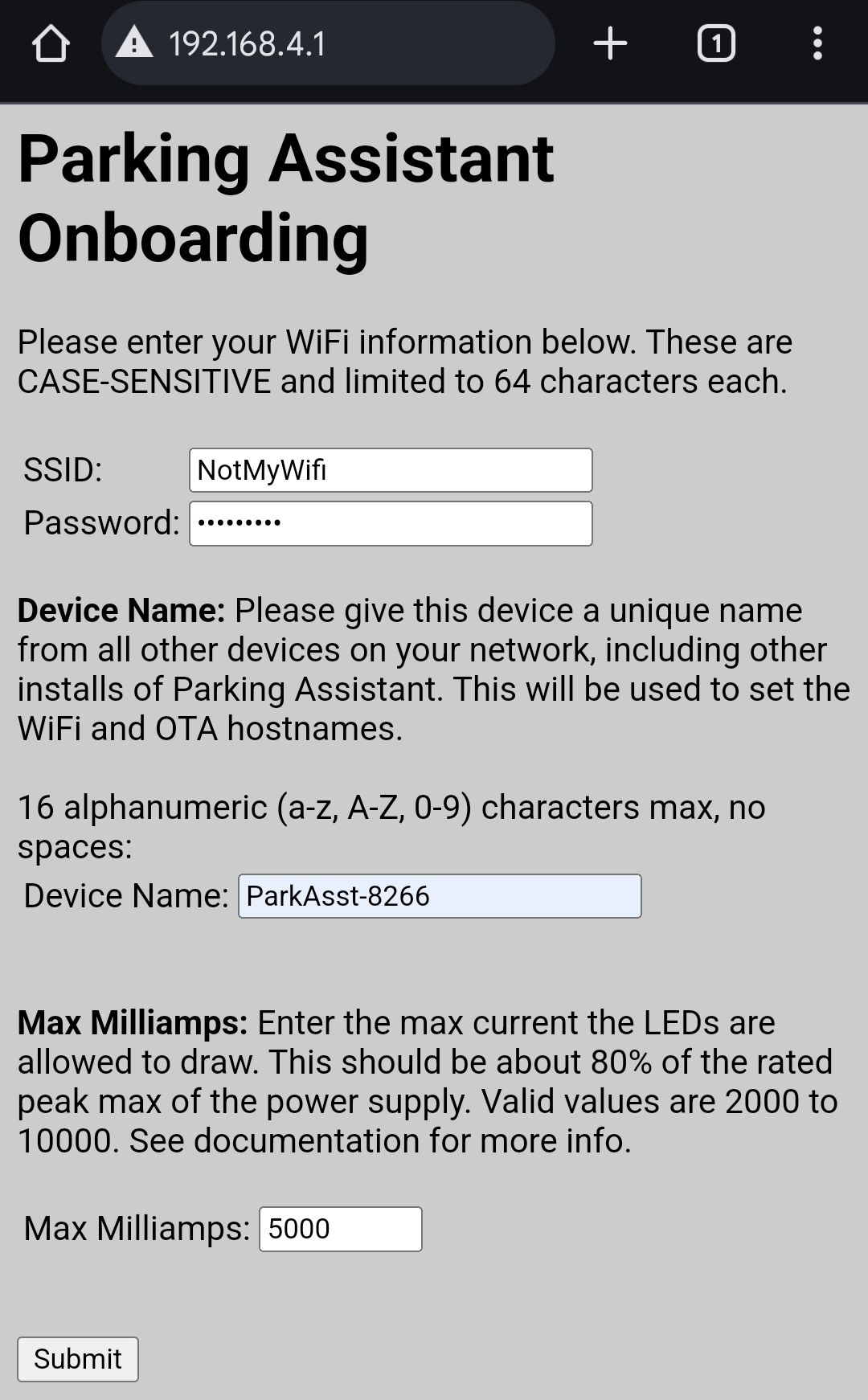
After connecting the the hotspot, open a local browser and go to the IP address: 192.168.4.1. The following wifi setup form should be shown:
WiFi Credentials
Enter your WiFi name (SSID) and password. Note that these are case-sensitive, so enter carefully.
Device Name
Each parking assistant device on your local network must have a unique name. This is used for a number of internal connections, such as wifi hostname, OTA hostname and MQTT client (if MQTT is used). Having more than one device with the same host name may cause problems or result in errors with the parking device. You can enter any name you like, up to 16 characters max, but can only uses letters, numbers (A-Z, a-z, 0-9) and a hyphen or underscore. Do not include any spaces or other symbols in the device name. Note that to later change this name, you will need to perform a full reset via the web interface and complete this onboarding process again.
Max Milliamps
Introduced as an additional safety features beginning with firmware v0.50, the maximum milliamp setting will limit the amount of current (amps) that the LEDs can draw. You should generally set this to around 80% of the max peak rating of the power supply. For example, if using a 5V 10A power supply, you'd set the max milliamps to 8000 mA (10A x 1000 x 0.8 = 8000). Like device name, if you need to change this at a later time, you will need to reset and onboard the controller again.
Click "Save" and the controller will restart and attempt to join your wifi network. If successful the hotspot will disappear and your phone (or tablet/laptop) will disconnect and you can reconnect to your selected Wifi. Note if you have more than one WiFi network... your controller and the device you will utilize to access the web settings need to be on the same wifi network.
You now need to locate the IP address assigned to the controller by your router. This will vary based on your particular router, but here is a sample from my router:
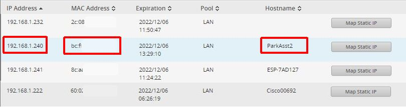 |
| Click for larger view |
The controller will attempt to join your wifi using the device name you entered as a hostname, but your router may not recognize or accept this host name. If you don't see a device with this name, then look for the MAC address you (hopefully) copied down when flashing the original firmware. If you cannot find either the hostname or MAC address, check and see if the controller is once again broadcasting its hotspot. If so, that means it failed in connecting to your wifi network. Connect back to the hotspot and repeat the wifi setup, assuring you enter the wifi password correctly.
Once on your wifi and you have the IP address, all future settings, options, upgrades, etc. can be done via a web interface. You will only need to repeat this step if you change your wifi or if you perform a full reset of the controller via the web interface.
Settings, Options and the Web Interface
See the Github wiki for full information on settings, options and other features of the controller. I'm only going to touch on a couple of items here.
Parking Zones
Many of the options and settings work on the concept that the controller uses four separate "parking zones" as your vehicle moves closer to the sensor:
 |
| Click for larger view |
1. Wake Zone: When your vehicle first enters the edge of the wake zone (farthest zone from the sensor), the LED strip will light up in a solid color (set by you - shown as green above) to let you know the system is awake and actively tracking the vehicle.
2. Active Zone: As soon as the vehicle enters the active zone (shown in yellow above, but again, you can specify the color use), the LEDs will use the effect you've selected to indicate the car is approaching the next zone. For example, when using the "Out-In" effect, the LEDs will light up starting on the outside edges and continue lighting up towards the center as the vehicle approaches the desired parking spot. Other effect are available as well, and these are described in the Github wiki.
3. Parked Zone: This is the desired final parked location of the vehicle. When the front edge of the vehicle enters this zone (shown in red above, but again you specify the color), the LEDs will all turn solid. How wide you make this zone will depend upon your particular situation, but if at all possible, a parked zone width of at least 6" is desired. Otherwise, it may be hard to precisely stop between the active and back up zones. Also recall that if the front of your vehicle has some curvature, the reported distance of the sensor may vary based on the left/right position of the car as related to the sensor.
The variance will depend somewhat upon the curvature of your vehicle(s) and how consistently the driver parks the vehicle left/right of the sensor. For this reason, you should make the parking zone as wide as possible while still having the car in the desired parking location.
4. Backup Zone: If the vehicle pulls too far forward, the LEDs will begin to rapidly flash (color of your choice), telling the driver to backup. The LEDs will continue to flash until the vehicle leaves the backup zone.. or until the parking timer expires.
A note on the active zone size and the sensitivity of the LEDs:
Your initial inclination might be to make the active zone as large as possible. But in actuality, a smaller active zone means the LED lights will be more 'sensitive' to changes in distance.
For example, let's say you have a total of 24 LEDs and you set the active zone distance to be a total of 8 feet (96"). This means a new LED will light up for each 4" traveled by the car. However, if the active zone is reduced to 4 feet (48") a new LED will light up for every 2" of travel. The greater sensitivity can be helpful as you approach the parked zone... especially if you have a shallow park zone.
So, you may want to experiment with different active zone differences, but as a general rule, you may want a wider wake zone and a narrower active zone to provide better sensitivity for the driver.
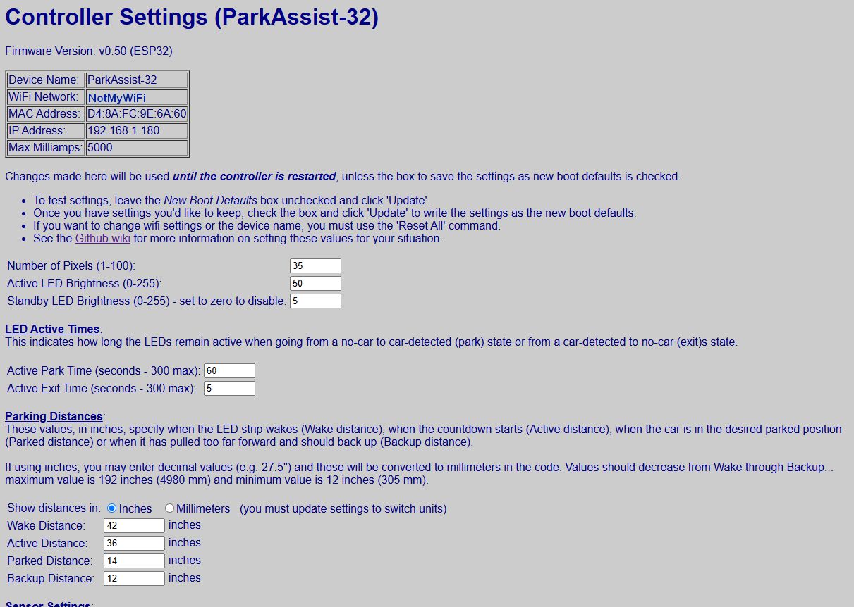
Web Interface and Settings
The web interface allows you to set many of the options (and more) discussed above You can, for example:
- Specify or change the number of LEDs, along with both the active and standby brightness of the LEDs
- Set the time the LEDs are active for parking and when a car exits.
- Specify colors to use for each of the four parking zones.
- Select from a list of different effects for the active zone
- Enable (or disable) side sensor lateral guidance (ESP32 only)
- Enable (or disable) MQTT functionality for use with home automations systems like Home Assistant.
- Reboot or completely reset the controller
- Upload future releases over wifi right from the web interface.
Once again, please refer to the Github wiki for details on the use of all these options. The Github repo will always contain the latest firmware version, along with any changes or additions to the features and options, including any new effects or colors that might be in a future release. Just one final note about the web configuration. Have just a bit of patience when loading the web site. Remember, this is running on an ESP8266, not a powerful web server, and that it is also running the parking process, listening for MQTT commands or OTA updates and other processes at the same time. It may take a few seconds for the web page to first appear, or to update when going from one web page to another.
Installation
If you've still been bench testing up to this point... and everything is working, it is time to finally install the parking assistant in the garage! Your installation may vary greatly from mine, based on a number of factors, but I'll cover my install in the event it might help you with yours!
 |
| Everything mounted, connected and working! The original Raspberry Pi version of the parking assistant can be seen at the far right. |
The first, and probably most important part of the installation will be the mounting location of the TFMini-s distance sensor. Ideally, you want this mounted at a height where it is going to reflect off of a solid portion of the vehicle, like the bumper and not the grill.
I simply measured the height to this part of my vehicle... about 18" in my case. Remember that the TFMini-s only has a 2° field of view, so the 'beam' is pretty narrow.
I then mounted the TFMini at this same height. As far as horizontal distance, ideally the sensor would be mounted so it is pointed at the forward most position of the vehicle (normally the center point), but this somewhat depends on the driver parking the car in the same left-right orientation each time (see curvature of the car above).
The only other somewhat important location for mounting is the LED strip.
You want the LED strip mounted close to eye-level for the driver. Too high and the driver may have to crane their neck to see the LEDs as they near the final parking spot... too low and they may disappear under the hood. Note that if you have limited wall space, you can also mount the LED strip vertically. In fact, the 'full strip' effect can be run in either direction from what would be the top of the strip down, or from the bottom up when the strip is mounted vertically, regardless of which end the wiring is connected to.
Lateral Guidance (ESP32 only)
The optional secondary sensor for lateral guidance may be installed on either the left or right side of the vehicle. Watch the updated video to see how lateral guidance works.
The above diagram shows the sensor on both sides, but obviously you only need one sensor and the left/right side will be determined by your particular situation. It may take some experimentation to find the optimum spot for the side sensor depending upon where lateral guidance is most important for you. Note that the side sensor/lateral guidance is only enabled when a car is in the Active Zone. As a general rule, you probably want the sensor closer to, but not extending into, the parked zone. However, if your particular situation requires guidance earlier in the parking process, the side sensor can be moved back further in the Active Zone towards the Wake Zone.
For height, you want to position the side sensor near the mid-height of the vehicle's body. Too high and it my shoot over the hood or through the window. Too low and it may actually return the distance to the floor or for high ground clearance vehicles, the distance under the vehicle. Again, some experimentation may be required. When determining the side sensor mounting location, you may wish to adjust the left/right detection distances in the settings to make the testing process a bit easier. You can always return to the settings to finalize the actual distances after the sensor is mounted.
The location of the controller and power supply are totally up to you, based on your configuration, location of AC power, etc. Just assure you manage any cable runs so they don't pose a trip hazard if located near a door like mine. In all honestly, I made my cable runs a little too long. If this was going to be a permanent installation for me (it's not... it was really done just for this blog and related video... I know, nuts right?), I'd probably go back and shorten some of those leads. But for now, my wife likes and has become accustomed to the Pi version. And since it still works just fine, I'll likely keep that one. But this one was definitely cheaper to build and easier to setup and configure.
Testing and final tweaking
Once everything is installed, it's time to get all the settings configured and tweaked for your vehicle. I highly recommend you start out with a large piece of cardboard, a trash can on wheels or other flat surface to set the initial settings instead of using your car. I can't be held responsible if you crash your car though the wall of the house because the settings were incorrect... or if the system doesn't work as expected!
The web interface allows you to quick make temporary changes and test them before writing them permanently to the settings. So, using your temporary 'car substitute', enter some initial distance values for the various parking zones and test them. You can also play around with colors and effects at this point if you want.
Once you have the settings pretty close, then (and only then) should you try it with a vehicle. If you will be parking close to a wall in the final parking position, I'd also recommend having an observer on hand when you try the parked (and backup) zone settings for the first time. Once you are happy with the settings, simply check the box to make the settings the new boot defaults. Of course, you can always change the settings again if needed or desired.
Congratulations! You now have a reliable, configurable parking assistant (and it's definitely cooler than that tennis ball on a string hanging from your ceiling!). And if you have Home Assistant or another MQTT-compatible automation system, you can use the parking assistant as a vehicle presence detector for your other automations.
Future Development
Since this article and video were originally published, a number of improvements and enhancements, along with various bug fixes, have been made. These include, but aren't limited to:
- Ability to define a custom MQTT topic
- Implementation of Home Assistant Discovery. Click one button and your parking assistant will be added to Home Assistant with no YAML or other configuration required on your part!
- Mobile-friendly versions of all the settings web pages
- Optional Lateral Guidance
While I try to keep this blog up-to-date with the latest changes, you should always check the Github repo release notes and wiki for the latest information as changes made to the firmware may impact or alter some of the details provided in this article.
Depending on interest... and my available time and project load... I may continue to develop the firmware and add more new features over time. Let me know in the comments if you build your own and you have ideas for improvement or new features. Naturally, I can't guarantee that I'll be able to implement them... but I definitely won't if you don't ask! Of course, the source code is also available so if you are experienced with writing Arduino code, you can always fork the repo and make your own version and improvements.
Thanks for reading... let me know in the comments if you have questions!
Links
If you'd like to support future content on this blog and the related
YouTube channel, or just say thanks for something that helped you out, you can use any of my Amazon links to make a purchase at absolutely no cost to you. Or if you prefer to say thanks directly, you can buy me a one-off cup of coffee at:


This is an incredible project, and an even better documentation/tutorial...thank you! I am in the process of getting this project up and running, and have purchased almost all of the items you recommend, except for the TFMini. I was wondering how big an undertaking it would be to modify the code to prototype this with an HC-SR04 Utrasonic Sensor (I have several lying around). I have significant experience programming, but not much with Arduino (c/c++).
ReplyDeleteWith much thanks,
David
The biggest work would be removing the library for the TFMini and every place it is referenced, such as in the main setup routine. Getting a distance reading with the HC-SR04 is pretty simple and there are a lot of examples online as to how to do this with Arduino code. But all the rest of the logic should work, as it is just based on distance reading (in mm)... and that part of the code really doesn't care where the distance comes from. And all the rest of the code (e.g. web app, OTA updates, LED control, etc.) should work without modification. As long as you can find a way to get an accurate (and consistent) distance reading in the main loop, in mm, I believe all the rest of the code would work... but obviously I haven't tested it... although I did use the HC-SR04 with Arduino code to for the section where I compared sensors. Hope that helps! Let me know if you have follow up questions, and I'll try to help as best I can and as time permits.
DeleteI've branched the code and am updating it to work with SR04 Sensor. Testing today. I'll push a merge request when I get it worked out.
DeleteJust a follow up. While I appreciate that you are willing to do the work to make the system work with the HC-SR04, please note that I will likely not merge that into my current code set. This is for a number of reasons... first off, I do not want to remove any of the current functionality for the TFMini... as it is my preferred option. If an HC-SR04 option is added, then the code would have to have a way to determine which sensor is used (TFMini or HC-SR04), so that also means that the web or onboarding process would have to allow the end user to choose during the setup. Next, I am considering adding a side sensor for lateral guidance (not sure if this will be part of the existing system or a separate standalone system) and this will likely be an HR-SC04 because I need the wider FOV. So, this would probably mean two different versions of the firmware (one for TFMini and one for HC-SR04). Personally, I do not have the time (nor desire) to maintain two code sets. While I am happy to consider any PRs... my recommendation is that you release your own HC-SR04 version. I would be happy to link to that repo from within mine and point folks that really want to use the HC-SR04 to your release. But I really don't plan on supporting the HC-SR04 as the primary front sensor in my existing project and I'm still working on improving this code, so maintaining more than one version isn't something I want to consider at this time. I've already closed one issue requesting the HC-SR04 as something I won't be including any time soon.
DeleteMakes sense. I modified the code so you can use either sensor (select able through configs). The nice thing about the SR04 is that since it doesn't use the serial pin, you can monitor the distance it reads which was helpful for debugging. I also fixed a bug which makes the firmware unusable if you happen to reset the device without saving the config file first. It attempts to load values from the config file where the key doesn't exist, and just boot loops. I fixed this by defaulting the values to the ones shown in your blog. I'll push these changes and you can decide if you want to incorporate. It took me a solid 3 hours and 3 different ESP devices to figure out why when I pushed reset, it just loops forever :-).
DeleteSorry for delayed response (for some reason Blogger flagged this comment for moderation). First off, I greatly appreciate the effort and work you have put in.... especially in locating the potential boot loop bug.. I think I was actually hit with that once during development, but just reflashed the latest 'stable' version I had and chalked it up to a corrupted flash. But I think I see the problem now that you point it out... and I'm guessing the easy fix was to just give all the char values under the "variables for portal use" starting default values? Please let me know if was something else.
DeleteAs far as the HC-SR04... when you say 'selectable' through configs, do you mean by editing the .ino file, or is it something that the end user can specify either via the mobile onboarding or via the web app? I only ask this because my YouTube audience leans more toward the beginner-to-intermediate side and as I've found in the past with other projects, they don't want (or necessarily have the skills) to use the Arudino IDE, assure all the board support and libraries are installed and to edit, compile and flash the code themselves. They want a compiled .bin file that they can just upload via something like NodeMCU Pyflasher without having to deal with editing any code. So, if the sensor selection has to occur in the code, I'd be back to maintaining two versions... something I don't want to do (nor have the time to do) in this case. But if this is the case, and as I mentioned, if you want to roll it out in your own repository. I'll be more than happy to point folks that want to use the ultrasonic version your direction.
Thanks again for your work on this.. and finding that bug! I do appreciate it!
Thanks for the awesome project and detailed tutorial! The fix is in rows 967-1010 of my repo: https://github.com/mj514316/Garage-Assistant/blob/master/src/parking_assistant.ino
DeleteI just added |and then the default value.
This also has my SR04 changes. I can push to your repo if you want to merge. Basically added a few things to the .ino config that you have to use to switch. I thought about modifying the web server but ran out of motivation :-)
https://github.com/mj514316/Garage-Assistant/blob/master/src/parking_assistant.ino
Thanks for sharing your updates... especially the fix for the potential boot loop. Do note that the version you have modified is a couple of releases behind the current. v0.41 in particular, completely changed the onboarding process to remove the number of LEDs and add a device name. The device name is used for a number of items.... wifi hostname, OTA hostname, MQTT client, etc. and this was to resolve an issue where someone had more than one device on the same network. Prior to v0.41, multiple devices would have the same host name for wifi and OTA updates and MQTT client name (and MQTT requires each name to be unique). It also allows the user to specify the MQTT topic (so devices will not overwrite each other) and gave the end user an option to display distances in inches or millimeters on the web interface. v0.42 also made some minor compatibility changes and a few minor tweaks to MQTT. I don't know if you want to consider merging these latest release changes into your version.
DeleteI will plan on rolling out your fix in a later version, but as I mentioned, at least for now, I'll probably stick with just offering the TFMini version... at least until that time that a user can possibly select via the onboarding and/or the web interface. Thanks again for your work... and sharing what you found.
Makes sense. Got everything working today, this was my wife's Christmas present. One more consideration, change the minimum distance from 12 inches to 1 inch. My garage is very very tight and I needed to set 5inch backup distance and 7 inch park distance :-). Merry Christmas, thanks for all you do!!!!
DeleteMerry Christmas.... and glad you got it all working. I'd happy lower the minimum distance if I could... it's not a limitation of the application, but a limitation of the TFMini. If you recall from this article, the minimum reliable distance for the TFMini is 30 cm (about 11.8"). And my testing showed that to be true. Below those distances, the TFMini either continues to report 30 cm, or throws an error code. Continuing to report 30 cm can be especially troublesome if the park distance is set lower than this, as the driver could keep pulling forward until they hit the sensor (or the wall!). That's why, as an extra precaution, I set the minimum value just slightly higher than the TFMini minimum... at 12" (30.5 cm).
DeleteThe only realistic way to get a lower distance is to move to the ToF sensor or ultrasonic, and give up both range and signal stability. I do know that someone forked my version and replaced the TFMini with ultrasonic, but it currently requires that you edit the source code and compile/install your own version via the Arduino IDE. I have not tested it so I can't say if or how well it works, and the forked version was at least 2 releases behind mine (soon to be 3, as I am about to roll out an update). So, there's that. I hope you can find a way to make the existing version work, but as I mentioned, I can't really lower the minimal distance due to the TFMini.
The concept of 'wake-up' requires a constant powered wait state. Additionally, the system might trigger with no car and someone walking by. Instead, what if the system was 'woken' when the garage door was in an open state. I cannot imagine a situation in which this system is used where the door isn't open (allowing the car to enter).
ReplyDeleteWith the obvious need for a garage position sensor, what would need to be altered to wake the system on door open and sleep on door closed?
You are correct... however, there are a few 'checks' built-in. First, if the system is in a 'car detected' state, the system will not wake up if there is motion in front of the detector... the system has to first be in a no-car state, then detect an object within the parking zone range to wake (except when changing settings, which wakes the device). And even then, it looks for 2 or 3 consecutive readings before triggering, so is actually is possible to walk across the sensor's path and not wake it. Furthermore, if it is woken by someone walking in front of it, it only stays awake as long as an object is still detected. It you walk out of view, the system will go right back to sleep in whatever time you have specified for the exit time (as short as 1 second).
ReplyDeleteHowever, to do what you are specifying and having the system wake and sleep based on the position of the door, there are a few different ways this might be accomplished (assuming there is a door sensor switch of some sort). One, you could use a 3rd party system or automation hub like Home Assistant, and use MQTT to publish a message to the controller to wake/sleep the system. Alternatively, you could wire the switch to to ground and a GPIO pin on the controller and use that as the wake/sleep source. Both methods would require modifications to the current firmware code (freely available via Github if you want to use it). And the second method would require finding a way to route the wiring from the door switch to the controller without interfering with the door opening/closing. There may be alternate methods as well... but those are a couple that pop into mind. If you want the entire system shut off, then you could use a smart outlet to kill or enable the power to the power supply based on the door state (again, via a separate automation system). Just note that it can take anywhere from a few seconds to up to 30 seconds for the system to power up and connect to your wifi...(the delay is primarily the amount of time it takes to join your wifi, and connect to your MQTT broker if that is enabled.. and that can vary).
Very insightful response. You have obviously thought this through. Great job - I am acquiring the shopping list as we speak. Thanks!
Deletecan i follow this guide but instead of a D1 mini can i use a spare esp8662 ive got lying around? i really want to do this as my next project.
ReplyDeletePossibly. Others have reported success using the ESP8266 NodeMCU... while others have reported being unable to get theirs to work. The latest release of the firmware attempt to improve compatibility with more NodeMCU boards, and while most boards should work fine, I can't promise that all of them will as there are many versions from many different manufacturers and I simply can't test all of them. You might take a peek at this issue in the Github repo: https://github.com/Resinchem/ESP-Parking-Assistant/issues/7
DeleteIf you do try, let me know whether your version/ESP8266 board works with the firmware or not (and which specific board it is).
Thank you for this awesome project. I have just setup one in my garage. For now, I used an iPhone cardboard box for the components and the LiDAR, which still looks fine. I will look at having a permanent solution later.
ReplyDeleteThanks again!
You are very welcome! Glad it is working out for you. My wife loves the one for her car. Thanks for letting me know that you successfully built the project. I love to hear when others are able to implement one of the projects that I shared.
DeleteHi, I need some help here. I kind of connected everything but I can't find a way to uload the .bin file to node-mcu. I don't know how to use the python script given on Github while there is not legit NodeMCU PyFlasher I could find. I am using HC-SR04, which pin should I connect to NodeMCU for trig & echo? Hoping for your help, thank you!
ReplyDeleteThe code will NOT work with the HC-SR04 as written. It was designed and includes libraries for the TF-Mini. Substituting the HC-SR04 requires modifying the firmware code as it communicates with the ESP in a different manner. If you want to use the HC-SR04, then you might check out the forks of this repo. I believe someone did fork this project and rewrite it for using the HC-SR04. However, if you opt to use that version, you would need to post your questions or issue there, as my version only works with and supports the TF-Mini sensor.
ReplyDeleteI can't say for sure. It depends on whether the communications with the TF-Luna has changed or is different than the TF-Mini. There was initially a change in communication with just different versions of the TF-Mini, so it's really hard to say whether you can use the TF-Luna with the existing code or not. I'm sure the code could probably be modified to work with the Luna, but since I don't have one, I can't tell you for sure what would need to be modified or how. But let me know what you find.
ReplyDeleteThank you for this great project. I am putting together the materials to complete this and just curious on ESP8266 vs ESP32 for this? Wasn't sure if there was any performance advantages of an ESP32 or should I stick with the 8266?
ReplyDeleteThere wouldn't be any real advantage to the ESP32, as the app doesn't take much processing power. You could certainly use an ESP32 if you like, but it would require updating the Arduino libraries in the code for the ESP32 as some of the libraries used are not interchangeable between the ESP32 and ESP8266. But I don't think you'd get any real "performance" boost by doing so.
DeleteThank you so much for the speedy reply, I will proceed with the ESP8266 and let you know how it goes/
Deletethanks this is a great project i was wondering if it would be possible to use the same led strip to indicate that the garage door is fully open my wife has backed in to the door twice right now i am using a sonoff s31 plug with a night lighted plug into but this would be a great feature to add you would only need it as long as the the car is parked in the garage thanks again
ReplyDeleteSomething like this is certainly possible, but it will require changes to at least the firmware code... and maybe the hardware depending on whether you want to wire the door sensor to the parking assistant controller or use a wireless sensor and something like Home Assistant/MQTT to communicate to the controller to turn the LEDs on/off based on door position. It's a feature I can add to the list of enhancement requests, but to be honest I don't know if or when I might be able to implement it. However, the source code is out there on Github, so you could always clone/fork the code and attempt to add door sensing to the firmware yourself... I'd be happy to answer any questions about the code if you want to attempt it, but I just don't know when I'd have time to do it myself.
Deletethanks for the fast reply unfortunately i don't know anything about writing programs or code but my son and son-in law are programmers so i will ask them and i think in my situation i would only need to change the code i use a sheely1 for my doors but still great project i am going to do the lights on the stairs next my grand kids will love it
DeleteHow would some of the newer millimeter wave radars (like the LD2420) compare in this use case to the LIDAR?
ReplyDeleteI haven't tried one with the parking assistant so I can't say for sure how well it would work, but it would require substantial modifications to the firmware to work with something like the LD2420. I think a few challenges would be the high minimum detection distance of the sensor (shown as around 2.3 feet for LD2420). You'd also have to define the proper "gate" so that other objects aren't detected since the FOV range for the LD2420 is shown as around 60°. I've used mm wave detectors with ESPHome, but not with Arduino code, so I'm not sure what all would be involved to get the mm wave detector to 'zero in' on only the parking zone and not other objects. I think it would be a bit more involved than a standard distance sensor. If you do get it to work, please let me know!
DeleteHow hard would it be to convert your code to work inside of ESPHome? You might be able to mount the radar higher looking down to prevent needing the <2' minimum distance.
DeleteWell, since ESPHome compiles using Arduino code, it is certainly possible, but I don't think it would be easy based on how the logic works. First off, last time I checked, the TF-Mini isn't supported in ESPHome, so you would need a different sensor (and any caveats that come along with that).
DeleteNext, angling the sensor down would limit seeing the car "approaching" (see the zone description above) and getting closer to the sensor. Instead, if mounted looking straight down, it would likely return the measured distance to the floor until the car enters the sensor FOV at which point, it would be measuring height... first to the hood, then the roof. Angling would reduce this, but any sort of angle is going to limit/alter the measured distance. The sensor really needs to be pointed down the approach path for best accuracy. You *might* be able to do something with the various gates on a mm wave sensor, but I think that will get complicated really quickly and would likely involve writing a lot of custom Arduino code, even in ESPHome.
There are obviously other ways to create a parking assistant other than what I've done here. But my code is pretty much written to work with the TF-Mini installed as shown. I may revisit the project at some point and make some improvements/add features (like ESP32 support), but will unlikely do anything with other sensors, platforms or alternate installations.
Great project, thank you! I would like to ask, is the WLAN login mandatory? There is often no WLAN signal in the parking garage. Can I skip the WLAN login and manage the settings directly from the device's own hotspot
DeleteCurrently, the firmware requires a WiFi connection. If a WiFi connection isn't established at boot time, the system begins broadcasting the hotspot and waits for onboarding. It doesn't even load the rest of the firmware (e.g. the web server) until a WiFi connection is established.
DeleteIt is theoretically possible to use the hotspot as the connection for the web settings, but this would take a pretty substantial update to the current code and the way it works. This isn't the first time I've had a request for a 'no wifi' version so I will certainly take a look at providing a non-WiFi option, but I can't promise when I'll get around to it.
While I haven't tested it, it might be possible to use two devices (like two phones or a phone and tablet) to onboard the system and modify the settings. Have one of the devices broadcast its own hotspot. Then using the second device, onboard the controller to the first device's hotspot (just like it was normal wifi). Once onboarded, you can also have the second device join the first device's hotspot. You'll need to use the first device to get the IP address of the controller, but once you have that, you should be able to use the second device to reach the web settings page and make any required changes. What I don't know is if the system will continue to operate if the hotspot then goes away. Obviously you can't use features like MQTT when using the process (the controller would need to 'talk' to the MQTT broker via WiFi). And if the controller restarts or reboots, you'd have to repeat the two-device onboarding each time. Not ideal, but it might work until I am able to provide a non-WiFi option. Again, I haven't tested this process (I'll try to do so something soon), so I don't know if it will work reliably or not.
Hi, just want to introduce myself how your works have being inspiring me and my home projects, it’s started by finding a way to gift a token of appreciation to a friend who has everything. One day he specifically looking for a raspberry pi so that he could run a mini server for his smart home. I got interested and got one for him and one for myself. Since we both are living in the country that least developed and very difficult find readily available retail items this was like a Christmas for me. Trust me that’s the first time heard about raspberry pi or python or c++ let alone coding lol.
ReplyDeleteIm kind of a person that who always want to customize myself and do want something more. Though im using home assistant I’ve never understood about Mqtt till I find your YouTube video for one of my project. Its just a water level controller which has TTGo T-1, A02YYUW UArt version, two YF-B10-S and water leak detector (I haven’t add in yet coz it will be a secondary fail safe) and a buzzer. One of the flow sensor is to check if there is incoming water for the motor to identify and cut of if necessary and one is for showing outgoing usage to display. After seeing your video I’m now starting to work with web configuration and auto publish. I just want to pre inform you to help me if I face some brick wall. Thanks in advance 🙏🙏🙏
I'm glad my videos have been helpful! The whole reason I started the YouTube channel and this blog was to try to help others that are just getting started. While there is a lot of info out there, I found that when I first started out (I started out with the Raspberry Pi as well... with my first one becoming my full sized coin-operated arcade machine), I wanted to learn and understand and not just copy something I saw on YouTube. But many how-to videos neglected to cover the why... they just showed the how. So I try to explain the 'why' as well as the 'how' in most of my videos.
DeleteBut I'm always happy to try to help out others by answering questions if I can. So always feel free to ask!
Just getting to implement this, retirement offers so many fun opportunities to just play. Thank you for all your posts/videos.
DeleteSimilar to others I wanted to toy with this with different devices. And as someone who worked on software used by hundreds of millions for decades, re-use and extensibility are ingrained into my coding being. As such I have restructured the project into classes. A "Distance" class (Can be configured for one of many devices, the tfmini in the project, I added a sonar, can easily add others. Once configured, it simply reports the current distance), a ParkingLEDs class (right now the parking zone logic is in here, I may break that out, has all the LED configuration and display logic). Currently the sleep/wake functionality is still in the main code, I have goals of breaking it out into a "SleepWake" class. And then next on my list is making all the webpage and persistent storage and automation code based on virtual classes so these classes can be used by other applications without having to jiggle the code.
It's been a LOT of fun, rekindled some of my coding passions from long long ago... I thank you so much for that!
CarDetected" class (takes the distance inputs and normalizes them, removing noise, etc)
That's fantastic! I'm actually pretty new to Arduino/C++ coding and have learned a lot (most of my history is with VB/ASP/.NET and SQL Server). In fact, I overhauled a LOT of the code when I updated the project to support the ESP32 and added lateral guidance because I had learned so much more since I wrote the original version. I'd love to see what you did when finished if you publish it out on Github or somewhere... let me know!
DeleteI think the biggest improvement I'd still like to make is to get all those HTML strings out of the main code and put the HTML into SPIFFS. That alone isn't all that difficult. Where I run into potential problems (and maybe there is a solution) is how to "package" it up into a single .bin or installation file. I know it can be done via the Arduino IDE, but this is one of my more popular projects and a lot of beginners have built this as one of their first DIY projects (and have never even used the IDE before). The biggest issue most beginners have is getting that initial flash correct. So I haven't tried to split out the HTML for fear of making the initial installation more difficult or complex. Seems like if I try to do anything with partitioning when I create the .bin file, then it won't flash correctly with standard desktop flashers. So at this point... if it isn't broken...!
But I'd love to see what you do with the classes if you can share it at some point. I'm always open to learning new things about Arduino... as I still consider myself no better than beginner-intermediate at this point!
Love this project and all of the work you do to help and inspire us!
ReplyDeleteHave you had any success with any ESP32 boards that support an external antenna? I get poor reception in my garage and have been pulling my hair out with an ESP32-DevKitC-VIE board. I had to change the GPIO pins for the TFMini-S, which worked a charm, but the LED's give me nothing.
I've used the ESP32-WROVER (all models) and ESP32 Dev Module boards in Arduino IDE for compiling. Compiling goes ok, but no joy on the LED's at all.
Hmmm... I haven't used an ESP32 with an external antenna, but for the firmware it really shouldn't make any difference as long as it is a 'standard' ESP32. Do any LEDs light up at all during the boot process? There is a sequence of LEDs that should light up during the boot (see Wiki). If you aren't seeing these "boot" LEDs, then it points to a problem with either the LED wiring or the type of LEDs (the firmware expects WS2812b LEDs). If you see the boot LEDs, but after the boot, the LEDs don't seem to respond, that generally points to a setup, measurement and/or firmware issue. Let me know what you see from the boot process. And I'm assuming that you can reach the web interface at an IP address on your local network at this point? I'm happy to help troubleshoot, but I need a bit more information as to exactly what you are seeing and what you have tried. I'm also curious as to why you needed to change the TF-Mini GPIO pins.
DeleteThanks so much for the speedy response. The LED's are standard WS2812b's and everything works properly on an ESP32-Mini (I purchased the one you have listed above). The only reason for my shift to the ESP32-WROVER-VIE is for the external antenna. I've ordered an ESP32-WROOM-UE just to see if it's a "VIE" thing.
DeleteWhen I power on the ESP32-WROVER-VIE I get no LED's illuminated at all. Access to the WebGUI works perfect as does the Calibration button for the TFMini-S.
I'm going to do a little more poking around at other GPIO pins on the VIE as I had to change GPIO 16 and 17 (to 5 and 18) because they're used "internally" on the WROVER module apparently.
From the documentation "The pins GPIO16 and GPIO17 are available for use only on the boards with the modules ESP32-WROOM and ESP32-SOLO-1. The boards with ESP32-WROVER modules have the pins reserved for internal use".
I have a gut feeling that the voltage provided out of the VIE for the LED DATA pin may be significantly higher than from the ESP32-MINI, so will start there.
OK... good to know that you had the system working with an ESP32 mini and that you are getting the web site to display with the "VIE". This means the firmware is operating properly. I know you've already figured this out, but the problem is obviously an issue with the LED data signal of some sort. Trying a different GPIO pin is the first step. Naturally you'll need to change it in the source code and recompile, but apparently you've already done that when you changed the GPIO pins for the TF-Mini. If you have a pinout listing for that particular board, try selecting a digital GPIO pin that isn't involved in any strapping operations. And obviously assure you have the brightness settings at set at non-zero values and saved as your boot defaults.
DeleteUnless it is a really strange board, all GPIO pins on the ESP32 operate at 3.3V. If anything, the voltage would be too low for the expected 5V signal of the LEDs. That's why I generally include a logic level shifter to 'boost' the GPIO pin signal from 3.3V to 5V... but you can often get by with the 3.3V as long as the data line is kept short to minimize voltage drop. Definitely let me know what you find... and I"m happy to try to assist further if I can.