

This article is a companion piece to the Curtain LED article and video but can also be a standalone project. Why is it a companion piece? Well, my intended use is to wear the shirt for special occasions, like Halloween, where the t-shirt will be synced to the LED curtain and both will display the same effect/colors and change from one to another simultaneously.
However, this article can also serve as a concept for creating your own battery-powered LED clothing or related projects. While part of this article can be considered "how-to", my method of applying the LEDs to the t-shirt could definitely be improved upon for someone with better crafting skills! So, use part of what I show here as just a guide for creating your own. You can also see a YouTube video of this project and then refer back to this article for specifics.
Concept and Goals
My primary purpose was to create a battery-operated wearable LED display that would work in conjunction with my LED curtain for special occasions or holidays like Halloween. The goal was to create a display that would sync both effects and colors with the LED curtain but could also operate independently... even in a situation where WIFI might not be available.
Parts List
As with most of my project articles, I like to start with a parts list of the items I used in my particular build and as described here or shown in the video. Your project might require variations or substitutions in some cases.
|
QTY |
Item |
Notes |
|
2 |
50 LEDs per pack |
|
|
1 |
|
|
|
1 |
|
|
|
1 |
|
|
|
1 |
Level Shifter (SN74AHCT125N) |
Only one shifter is
needed |
|
OR |
Level Shifter (I2C) |
|
|
1 |
|
|
|
1 |
|
|
|
1 |
|
|
|
1 |
|
|
|
1 |
|
|
|
1 |
|
|
|
1 |
|
|
|
1 |
|
|
|
1 |
|
|
|
1 |
|
|
|
1 |
Only needed for
testing |
|
|
|
|
|
Some of these links may be Amazon affiliate links. Use of these links will not affect your pricing, but as an affiliate this blog may earn a small commission if you make a purchase.
The LEDs Used
For a battery-operated wearable project, standard WS2812b LED strips obviously won't work. For one, these LEDs are going to draw too much power in any meaningful quantity to be battery friendly. And second, LED strips aren't very "shapeable" for attaching to fabric or clothing. Even the LEDs used for the curtain would likely drain any battery quicker than desired... and the LED themselves are still a little too large.

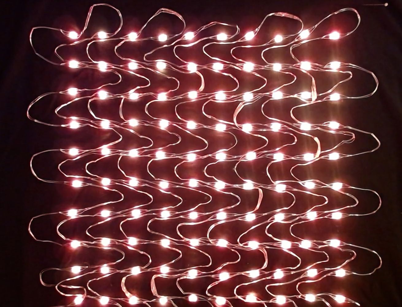
Instead, I'm using these very small fairy lights. These are RGB LEDs and in fact use the same WS2812b chip, meaning we can use the same type of controller and firmware (WLED) as with the other two types of LEDs.
However, these small pixels should draw significantly less power (I'll check this below) and have very thin, flexible, yet shapeable wires. All this should make them ideal for shaping into a matrix pattern on the front of t-shirt that mimics the LED curtain.

These 5V LEDs come in 5 meter (16.4 feet) lengths of 50 pixels, meaning the pixels are spaced 100 mm (about 3.9") apart.
LED Wiring/Pin Outs
While the small thin wires are ideal for creating unique designs or a wearable display, they do make identification of the individual wires a bit tricky.

Unlike LED strips where the 5V, data and ground line, along with the data flow direction are clearly indicated at each pixel, making cutting and joining sections of strips easy, there obviously isn't room on the tiny wires of the fairly lights to provide this type of labeling.
However, like both the LED strips and those LEDs used for the curtain, each individual string of lights has a JST connector at the beginning and end. These are used to join multiple strings together.

The JST connector does indicate the 5V line via a red stripe. But what if you want to cut off the JST connectors and join the strings directly together? That's what I needed to do in my case. I will be using two strings for a total of 100 pixels, but I don't want these big bulky JST connectors dangling from the front of the shirt. So when you cut off the JST connectors, how do you identify the proper wiring? Turns out, these pixels actually are labeled like LED strips, albeit in a bit less obvious manner.
 |
| Click to enlarge |
If you look closely at each pixel, you will notice a small colored dot (the dots are actually small triangles if you look at them under a magnifying glass). These dots alternate in color: red-green-red-green. These dots always appear on the same side/same wire along the string. This actually indicates both the ground wire and data flow direction.
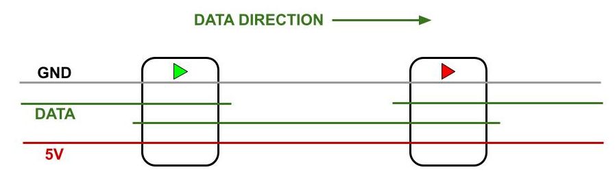
This information will allow me to cut off the JST connectors and rejoin the two strings while maintaining proper polarity and data flow direction. More info on how to directly connect strings together is covered below.
Determining Power Draw and Battery Life
Before designing the controller and selecting a battery source, it is important to get an idea of how much power (specifically the amps) will be used by 100 of the fairy LEDs, plus the power needed by the controller.

To do this, I simply created a breadboard version of the WLED controller and connected two strings (100 pixels total) to the controller. I used a 5V 10A power supply (so the power draw would not be limited by the supply... the brightness limiter in WLED was also disabled). I used a couple of temporary USB connectors to connect a USB tester between the power supply and the controller. The LEDs are also being powered through the breadboard.
 |
| Click to enlarge |
When the controller was powered on, but the LEDs were switched "off" in WLED, the standby power draw was about 170 mA. Do note that LEDs actually draw a little power even when turned "off" if they are connected to power. In my case, the controller draw was around 70-100 mA and the rest was from the powered "off" LEDs.
 |
| Click to enlarge |
When the LEDs were turned on at white 100% brightness (this should be the max draw), the system drew right at 1A. But most other colors and effects (at a more realistic 50% brightness) required less than 500 mA.
 |
| Click to enlarge |
In fact, many effects were under 300 mA. So for the purposes of the power supply size and the connections, we need everything rated for 1 A (the power supply should ideally be able to produce at least 2A so that it is not operated at the peak max rating). In terms of calculating battery life, we can assume that continuous operation of effects at 50% brightness will draw no more than 500 mA.
Voltage Drop and Power Injection
If you are familiar with LEDs, you already know that each LED provides a bit of resistance (along with the wiring, connections, etc.). Eventually this resistance causes the voltage to drop low enough that the LEDs cannot fully light up, resulting in dimming, shifting colors (towards red) and eventually LEDs that cannot light up at all. This is overcome by injecting an additional 5V into the LEDs at the end of the strip or at some midpoint. I needed to test this as well to see if my 100 LEDs were going to need power injection.

The good news is that even at 75% bright white, there was no noticeable fading or significant dimming. A slight shift towards pink could be seen at 100% brightness, but it was not noticeable at all when using other colors and/or effects. At 50% brightness, there was no impact at all, which is where I will likely run these lights.
These tests resulted in a few decisions. First, at no more than 1 amp max, we can run the power for the LEDs through the ElectroCookie board (but NOT through the ESP pins)... more on this under the controller build below. Power injection won't be needed, which will greatly simplify the wiring needed on the shirt. Finally, we can now select a battery source based on required amps and desired estimated run time.
Estimated Battery Time
From the above information, we can calculate estimated run time based on the size of the battery.

10,000 mAh / 500 mA = 20 hours!
Even allowing for inefficiencies or a greater than expected draw, I suspect I can get at least 15-18 hours off of a full charge. This will be more than enough time for trick-or-treating or any sort of other event or occasion.
AA Batteries
You might be wondering if you could power the system using 3 AA batteries, since 3 AA batteries connected in series would provide around 4.5V. With fresh batteries, this would probably be enough to power up the controller and LEDs, albeit with slightly less brightness and more susceptibility to needing power injection (due to the lower starting voltage). Even given that, the milliamp-hour rating for most alkaline AA batteries range from 1,800 - 2,700 mAh. Therefore:
1,800 mAh / 500 mA = 3.6 hours
2,700 mAh / 500 mA = 5.4 hours
So, in a perfect world, brand new batteries might run the LEDs continuously for around 3.5 - 5.5 hours. In actuality, it would probably be somewhere around 2 - 4 hours, possibly less because the voltage may drop too low to continue to power everything as the battery drains. My personal choice is to provide a power source that I know will run through an evening without needing to replace batteries. But it may be possible to use AA batteries if desired. I did not test this.
Building the controller
The controller is just a basic WLED controller that I've covered in other videos and blog articles, including these:
However, there are a couple of unique things about what I decided to build for a truly wearable/portable system.
First, I wanted to use an ESP32. This is primarily because I wanted to be able to sync to and use all the features of the LED curtain. Since that project used an ESP32, I wanted an ESP32 for this project as well. However, I really wanted the overall smaller size controller that normally requires use of the Wemos D1 Mini (ESP8266).

As you can see, the smaller D1 Mini at the top, along with an I2C level shifter would just barely fit onto the smaller ElectroCookie board. The larger size of the ESP32 Mini simply would not allow it to fit with the I2C shifter, so the larger ElectroCookie board would normally be required.
However, I wanted to be able to use the smaller controller and 3D print a "belt holder" for this controller, so it could be mounted on my hip when wearing the t-shirt (Links to the 3D .stl files for my enclosure and belt holder can be found at the end of this article).

This would require a bit of creative wiring and the substitution of the I2C level shifter for the smaller SN74AHCT125N shifter. Adding to the complication was the desire to power the LEDs from the controller board as well.
 |
| Click to enlarge |
Because there simply wasn't enough space/thru-holes on the small ElectroCookie board to mount the level shifter, this was attached with short runs of 22 gauge stranded wire, which is also used for all external connections such as to the power supply and LEDs. The other on board "point-to-point" wiring connections used 20 gauge solid wire.
The push button is entirely optional but gives you local button control of the LEDs and the ability to do things like toggle the LEDs off/on, change effects, etc. without needing to use a phone or computer.
Regarding the external connections, since I will be using a power bank, this means a male USB-A connector will be needed to plug into the bank. To do this, I simply took a USB connector and soldered lead wires that would provide 5V and GND to both the controller and LEDs.


The middle two pins (2 and 3) are for data. Since we only need power for this cable, those pins won't be used. Be sure to double-check that you don't reverse the polarity or you risk destroying your controller when you plug it in! Use a voltmeter or multimeter to verify if unsure.


I installed the latest build of WLED MoonModules onto the ESP32, which was the same version that I installed on the LED curtain. The installation of WLED is pretty straight forward and I cover it in other videos. Links to the various versions of WLED are provided at the end of this article and contain instructions as well, although do note that MoonModules is currently not available to be installed with the web installer but instead must be downloaded and flashed with a third party tool such as NodeMCU PyFlasher. Standard WLED will work just as well in this case.
Power Routing Options
If you followed any of my other blog articles or YouTube videos on LED lighting, you know that I stress that you should not normally route power for your LEDs through the controller board. This is due to the fact that the ElectroCookie board has small traces that aren't meant to handle larger current. However, since my install will draw only a max of 1 A at full bright white and nominally less than 500 mA for most effects at lower brightness, I did opt to run the power through the board.
 |
| Click to enlarge |
For anything around 1 A or less, you can run your power connections through the board (although you should still attempt to keep the trace distance between wiring connections as short as possible).
For something between 1A and 2A, you probably need to use the larger ElecroCookie board and bridge the power connections with wiring (20 gauge or larger) to help with the current.
For anything around 2A or greater, it is highly recommended that you split off the power from the supply and run a separate feed directly to the LEDs. You can, if desired, split off the separate leads at the board and feed the wiring under the board and out the other side, in effect still giving the same external connection configuration as my version.
But this is why it is important to know the approximate power use of your install so that you can wire correctly to support the amps the project might draw.
And as always, I recommend you create and test your controller build on a breadboard before soldering everything into place. I had done this previously when measuring the power draw of the system.
 |
| This test shows the I2C shifter. I'd later retest with the SN74x. |
Installing the LEDs
First and foremost, there are probably many, many better ways to apply LEDs to clothing than the method I used here! Someone with better crafting/sewing skills could surely do a better job. I'm only presenting what I did here as a concept for you to adapt to your own needs.
I wanted a matrix layout on my t-shirt (to match the patterns shown by the curtain). So, I opted to create a 10 x 10 square layout for a total of 100 LEDs. This is only 1/4 the number of the curtain, so resolution will be significantly lower, but I felt this was about the maximum number that I could place on the shirt and still be able to power it directly with decent battery life.

I started by finding the center of where I wanted the lights on the front of the t-shirt and marking of a 10" x 10" square with masking tape. I could then space out the rows and columns, making marks on the tape. I'd be spacing the LEDs 28 mm apart on center.
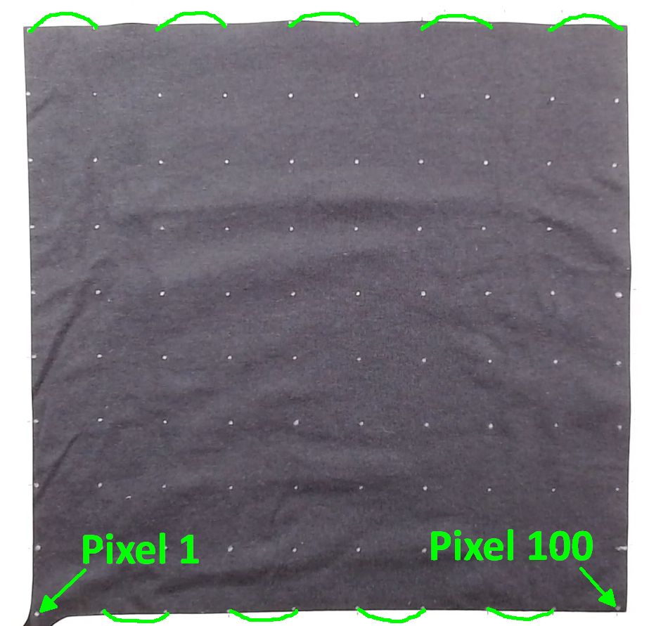
I started with pixel 1 where the controller will connect at the lower left of the shirt when looking from the front (it will be my lower left when wearing the shirt). This will allow a pretty short wiring run when the controller is worn on my belt. The pixels will be laid out in a 'serpentine' pattern, traveling up one column and down the next.
This is the same direction as the data flow travels (remember that with LED strips/strings, the data can only flow in one direction). Why is this important? Well, each fairly light string is 50 pixels and I am going to use 100. That means that two strings need to be joined together. While the strings come with JST connectors, my join will occur at the top of columns 5 and 6, meaning I'd have those bulky JST connectors (and a lot of extra wire) right under my chin. So I will be cutting off those connectors and soldering the two strings together (more on this below). For that, I need to assure I'm not only getting the polarity correct, but that I am maintaining the data flow direction.
Now it was time to start attaching the LED pixels. My initial thought was that I would use a combination of fabric glue and also sew each pixel into place. I placed a piece of cardboard between the front and back of the shirt and pinned the shirt to the cardboard. This ended up being very fortuitous as I initially did it just to keep the front of the shirt flat.

I began by using just a small dot of fabric glue under each pixel, shaping the wire as I went.

I found the best process was to 'pre-shape' the wire in approximate shape. The wire is flexible and will hold its shape, but you do have to use care as these wires are very thin and repeated bending could cause them to break. Even with the wires bent into the approximate shape, I found that just doing a couple of pixels at a time, adding a little weight (I used spools of 18 gauge wire) and giving them about 20 minutes of drying time before moving on worked best. If you try to shape the next wire/pixel into place before the glue has had a chance to set a little, they will slide out of position. So, I had to work slowly and give each pixel a change to bond before moving on to the next.
I then thought I would sew each column into place before moving onto the next. That lasted for about the first three pixels!

Due to my poor sewing skills and the fact that it was difficult to get to the underside of the shirt with all the pixels in place... and I had that piece of cardboard under the top side of the shirt, it became quickly apparent that it was going to take me days, if not a week or longer, to get all these pixels sewed into place.
I also found that once completely dry, the fabric glue was doing a really good job of keeping the pixels in place. For this reason, I opted to only sew the pixels in a few spots where I felt there might be stress points, such as the start of the strip where the JST connector was located.

And speaking of the cardboard, I mentioned that I only placed it under the front of the shirt to keep the shirt straight and flat as I worked. But it was fortuitous because as I discovered, the fabric glue had a tendency to soak through the shirt and a number of the pixels were actually glued to the cardboard as well. These popped loose easily (it reminded me of removing a 3D print from the print bed), but without the cardboard, the front and back of the t-shirt would have been glued together and it would have been much more difficult to separate them. For this reason, you will want to put some sort of protective layer under the front of the t-shirt. In hindsight, I probably would have placed a piece of something like wax paper over the cardboard to help with popping any residue glue loose.

I simply continued this process over a couple of days (giving each couple of pixels a chance to dry a bit before moving on) until I had all 100 pixels in place. Again, the important thing here is to try to keep the rows and columns aligned as best as possible with consistent spacing. I did test along the way with the controller and battery pack to assure I hadn't damaged any part of the string or any pixels during the installation.
But recall that this is two separate 50 pixels strings of lights, joined together. At the top of the above photo (between columns 5 and 6), you can see where I removed the JST connectors and joined the strings together. This is what I'm going to cover next. The JST connector at the end of the string (pixel 100) is not needed, so I simply cut that off and sewed this end in place.
Joining Fairy Light LED Strings
Joining together fairly LEDs is a bit more challenging than most other types of LED strips. Partially it is because the labeling of polarity and data direction isn't as obvious as with LED strips, but mostly it is due to the very thin wires and the need to remove the clear coating that is applied to these wires. This clear coating is needed to prevent shorting where the wires touch.

While not as obvious as LED strips, the fairy lights are actually labeled to indicate the 5V, ground and data lines, and the direction of data flow. I covered this above but will include the pinout diagram here for reference.
While the 'arrow's look like just small dots to the naked eye (at least to mine), this is still enough to assure that when joining strings we can maintain polarity and data direction.
Removing the very thin clear coating presents a bigger challenge. The wire and coating are way too thin to use conventional methods like wire strippers. Instead, this is the method that I used and found that worked consistently for me.

First straighten and separate the three wires a bit so it is easier to identify which wire is which. You can then snip off the JST connector.
Next, I applied just a very quick amount of flame (I used a simple Aim 'N Flame) to the very end of the cut wire. This is only for 1-2 seconds max. You just want to melt the coating off about 1/4" of the wire at the tip. But this thin wire conducts heat very rapidly. In fact, be careful not to burn your fingers! If you look closely, you should be able to see the insulation melt and curl back just a bit. If you leave the flame applied too long, you risk melting off too much coating (we need to re-insulate these wires after joining to prevent shorts) or too much heat could actually damage or destroy the LED pixels.
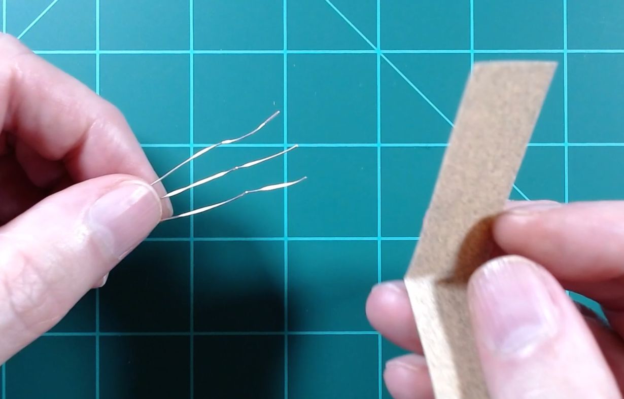
Next, use a small piece of sandpaper (I used 120 grit) to clean off the tip of each wire, removing any remaining insulation. Remember, you don't want to expose more than 1/4" - 3/8" of bare wire.

If you look closely, you should be able to see bare copper wire exposed. If not, keep sanding gently. Repeat this process until all three wires on both strings to be joined are prepared.

Assuring proper polarity and data direction and adding short pieces of heat shrink, the ends of the exposed wiring were twisted together. A small drop of solder was then added to each join. The twist was used instead of solder alone because I felt like trying to tin and solder each wire alone would require too much application of heat that was likely to melt additional coating from the wires. Instead, solder was placed on the iron and the iron just briefly touched to each wire to transfer just enough solder to keep the twists together. The heat shrink was then placed and quickly heated to seal each connection.

The LEDs were then tested. I gently moved the wires around and squeezed them together (so that they were touching) to assure the join was solid and no short would occur due to missing insulation.
And of course, the entire string was tested again after the installation of all 100 pixels was complete, the glue fully dried overnight and the carboard removed.
This completes the actual build process.
Putting it all Together (and putting it on!)
The t-shirt goes on pretty easily... and it was surprisingly comfortable! I was fearful that the wiring would be uncomfortable, but it is barely noticeable. Now, naturally you can't do a lot of bending and twisting, but even sitting was just fine when wearing the shirt.

Once the t-shirt is on, I can simply loop my belt through the 3D printed holder, insert the controller and make two simply connections... the JST connector to the start of the LEDs and the USB connector to the power bank, which I can then slide into my pocket.

Once everything is in place, the t-shirt can be pulled down and hides pretty much everything except for the JST connector. And at this point, the display can be controlled via my phone (more on this below).

The t-shirt was more comfortable to wear than I expected. The wires really can't be felt and it was easy to sit as well as stand (well, for sitting I did have to remove the battery pack from my back pocket).
Syncing to the LED Curtain
WLED allows you to sync two or more controllers together. By syncing, you can change the effects, colors, brightness, etc. on one display/controller and it will automatically change any synced devices as well.
Syncing does have to be set up and enabled. This is done via the Sync Interfaces button under the configuration menu.

Starting with version 0.13 of WLED, you can define multiple sync groups. This means all controllers within that group will send/receive sync commands. You can also specify two different UDP sync ports for communication. Any devices you wish to sync much have the same UDP port and be enabled for either send or receive in the same group.
In the picture above, this controller will send sync commands (but not receive) to other controllers with the same UDP port(s) that have the Receive option enabled for Group 1. It will receive sync commands from any controllers in Group 2 and both send and receive commands from Group 4.
You can sync brightness, color and/or effects. There are other options for syncing things like segments and bounds, but I'm not using those so I won't cover them here.
Once syncing is defined, you can simply toggle it on or off from the main WLED interface screen.

When enabled, the controller will begin syncing with any other controllers in the same group that are also enabled for syncing. Turning this button off stops syncing and the controller will again operate independently.
For my situation, I want any changes to the curtain to sync to the t-shirt, but do not want the curtain to change if something is changed directly on the t-shirt.

I first assure that both controllers are set to use the same UDP port(s). Since I only want my sync to go "one-way" from the curtain to the T-Shirt, I set the curtain controller to send commands via Group 1 and the t-shirt to receive on Group 1. This means that if I change a color or effect via the t-shirt controller, the curtain will not be impacted. However, the next change to the curtain will sync back to the t-shirt. I'm opting to not sync brightness. I can independently set the brightness on one device and it won't impact the brightness on the other.
Once the sync settings are defined, I can start syncing by toggling the sync button on for both controllers. If I want to stop syncing, I can just toggle off the button on either controller and the two devices will again operate independently until syncing is re-enabled.
There are many, many more syncing options. The latest versions of WLED allow you to sync to other systems like Hue, Hyperion and even xLights! See the WLED documentation for more details.
Using without WiFi
Since the t-shirt (or any other wearable you create) is battery-powered and completely portable, what happens if you want to walk the neighborhood during trick-or-treat time, or wear your shirt to a holiday gathering elsewhere? What happens if your controller cannot connect to wifi? No problem... as long as you have your phone!
 |
| Controlling the matrix down the street with no WIFI! |
While technically not absolutely necessary, I recommend downloading and installing the mobile app version of WLED onto your phone.

There are versions for both Android and iOS. Just assure you are downloading the official app by Aircookie (Android) or Christian Schwinne (iOS).
Whenever your WLED controller cannot connect to WIFI, it will broadcast a local access point (hot spot). If you plan on using your project routinely when out of range of your WIFI, you may wish to configure some options regarding the local WLED access point that you will use. These options can be found under the WIFI settings of the configuration menu.

You can optionally give the access point an SSID that will broadcast a recognizable name and make it unique from other WLED devices (the default is WLED-AP). You can also specify a password to connect to the access point if desired. If you do this, you will have to type the password into your phone each time you connect to the WLED controller when not using wifi. Or you can opt to leave the access point open with no password. Of course the risk with this is that someone else could theoretically connect to this access point and take control of your device, but the range of the broadcast AP is pretty short, so it's not like someone a half mile away is going to see your device broadcasting! This might actually be desirable in a situation if you want to let others control your device. The choice as to whether to use a password is yours. Blank out the password for none. Leaving the password blank does make it a bit easier to connect with your phone.
Next, you should define when and how this access point is broadcast. The default is if the device cannot connect to WIFI after booting. This means if you are connected to your WIFI and then move out of range (e.g. walk down the street), you will have to reboot the controller before the AP begins to broadcast. With the disconnected option, the AP will start to broadcast when the WIFI connection is lost. If you plan on using your device on a regular basis outside of your WIFI, I'd recommend selecting either Disconnected or Always ('Always' will still broadcast the AP even when connected to WIFI - you may wish to consider an AP password with this option).
Once the controller begins broadcasting an access point, simply use your phone's WIFI settings to connect to this access point.

Your phone may warn you that Internet connectivity is not available and ask if you wish to stay connected. If so, select the option to remain connected. Once connected, and depending on your device (and whether a password is require), you may be prompted to log in to WLED. If nothing happens, simply open up a browser on your phone and go to the IP address: 4.3.2.1

There is an option to set WIFI information, but instead just select the "To the Controls" option.

You now have complete control of all features of your device locally using the access point without any WIFI! Naturally some features, like device syncing that require wifi won't work, but otherwise all the features are available to you!
When you return to your local WIFI, the controller should automatically rejoin your WIFI. If it doesn't, a simple reboot of the controller should work. Note that you can do this with pretty much any of your WLED controllers, so if you wish to take one of your other outstanding WLED projects to a different location, you can use this same technique to control your display.
Alternate Method
After the initial creation of the video and this article, another creator named Quindor over at Intermittent Tech shared an alternate method of controlling the LED display when not on WIFI. His method involves 'flipping' the process around and using your phone as a WIFI hotspot and connecting the controller to the phone. This has the advantage of allowing your phone to continue to maintain an Internet/cellular connection. However, it does involve changing the WIFI settings your LED controller (and rebooting) each time you enter/leave your own WIFI, so it may or may not be a better method for you depending upon your particular use case. You can see his method in this video.
Conclusions and Final Thoughts
As mentioned at the start, someone with better crafting/sewing skills could likely create a much better final wearable product. But from the perspective of creating a wearable LED display that is battery-operated with exceptional battery life and can be used without WIFI, I feel like the project was a success.
In my case, the final project really has kinda' limited use. It's definitely not something that is going to be used on a regular basis. For one, even though the LEDs themselves are IP65 rated, my connections and installation method are definitely not waterproof. This means I have no good way of washing the t-shirt. At some point, the project probably will see an end-of-life and be recycled in some manner.
But let me know down in the comments if you've created either a battery-powered or wearable LED project and if you have any tips for others. And as always... thanks for reading!
Links and Additional Information
If you'd like to support future content on this blog and the related YouTube channel, or just say thanks for something that helped you out, you can say thanks by buying me a one-off cup of coffee at:
Thank you for your writeup. I'm working on a coat project for my wife and this was a great explanation.
ReplyDeleteYou are most welcome! Glad you found it helpful. My t-shirt has been a hit on Halloween night, so don't hesitate to ask if you run into any questions along the way with your project.
Delete