

Have you ever had a retail device that either became useless because the manufacturer went out of business... or one that started charging a monthly subscription for a previously free service? It happens all the time. And if it happens to you, your device is either a useless piece of plastic or you are forced to pay a "ransom" to continue to use a device you already purchased and own.
Many devices (but not all - see below) can be flashed with completely free and local custom firmware that avoids the need to use a vendor's cloud service (and share your data). Once this is done, no one can disable your device, make unauthorized changes, access your data or start to charge you a fee for continued use.
If you prefer to watch a step-by-step video of the following process, you can watch a YouTube video here.
While I will be showing a specific example here, the process is nearly identical for flashing most compatible devices. And I'll be covering the process for flashing two very popular firmware options... Tasmota and ESPHome. But the same process can be used for flashing something like your own custom Arduino code as well.
Parts List
As usual, I start with a parts list. There are some parts that will be common to most flashing processes, and a few that are specific to the example I'll be using here in this article.
|
QTY |
Item |
Notes |
|
|
USB-to-Serial Flasher (only one needed) |
|
|
1 |
Most common or |
|
|
1 |
Alternate version |
|
|
|
|
|
|
|
Jig and Connection Options |
|
|
1 |
This is a Thingiverse
link |
|
|
- |
|
|
|
- |
Alternate to jig |
|
|
- |
|
|
|
1 |
Optional but recommended |
|
|
|
|
|
|
|
Smart Plug Used in
the Article |
|
|
- |
With energy
monitoring |
|
|
- |
No energy monitoring |
|
|
|
|
|
Some of these links may be Amazon affiliate links. Use of these links will not affect your pricing, but this channel may earn a small commission if you make a purchase.
Selecting a flashable device
Not every smart home device can be flashed in this manner... or flashed at all. First, the device must be using an ESP-based processor (generally ESP8266 or ESP32), as this is what Tasmota and ESPHome run on... at least at the time of this article.
Many manufacturers have begun to either replace the ESP chip or to encrypt and lock-down their firmware so it cannot be overwritten. Why? They want your data. This is a revenue source for them. If you take your device that you paid for out of their cloud, they lose that data... and they don't like that.
Other manufacturers however, have begun to recognize the large Home Assistant and DIY market and have made flashing relatively simple... or have even begun to sell their devices pre-flashed with Tasmota or ESPHome (more below). Personally, I'd recommend supporting these vendors that support us... even if you aren't going to replace their default firmware.
Next you must be able to access certain pins on the device, such as V+, GND, RX and TX, to be able to write the firmware. Sometimes this requires disassembly of the device and other times the vendor makes these pins readily available (see Shelly). How do you know if a device meets the requirements for flashing custom firmware?
Luckily, both ESPHome and Tasmota maintain lists of compatible devices that is updated on a regular basis. If you are looking for a smart plug, switch, relay or light bulb, you can check out these lists before you buy the device:
Not only do these sites list compatible devices, they also provide any special notes that you might need to know along with configuration information that you will need to make the device function properly.
For my example, I'm going to be using a Sonoff S31 Lite smart plug.

I am selecting this device for a few reasons. First, it is compatible with both ESPHome and Tasmota so I can show the flashing and configuration process for both firmware options. Next, this device is easy to disassemble and reassemble as no glue is used. Finally, the pins needed for flashing are clearly labeled and easily accessible... it's like the manufacturer specifically made the device easy to flash for DIY'ers!
Note: There is also a standard Sonoff S31. The only difference is that the standard Sonoff S31 has power monitoring capabilities while the Lite version does not. For my particular project, I don't need power monitoring but it can be a benefit if you want to use a smart plug for things like dishwasher or washing machine notifications (video) because power monitoring can be used to know when a machine starts and ends, based on the power draw. The flashing process is identical and there are only slight changes in the configuration between the two devices to account for, or the lack of, power monitoring.
The process for most devices will pretty much be the same as described below. The primary difference will be the process used to disassemble the device and the location/connection method used for flashing the firmware.
Disassembling and Preparing the Device
The Sonoff S31 is very easy to disassemble and reassemble because no glue is used.
Disassembly

To begin, remove the gray end cap. This is most easily done by inserting a spudger or small flat blade screwdriver between the gray cap and the white housing. Gently pry and twist, working your way around the edges until the end cap pops off. This is not glued, but held with plastic retaining tabs.

Here you can see the end cap removed and the four plastic tabs that hold it in place. The best way to assure you don't break these tabs is to just work your way around the edges carefully... don't force too hard... and the cap will eventually pop off.

With the end cap removed, there are two plastic rails above and below the outlet prongs that simply slide off. This will expose three small screws.

Using an appropriate screwdriver, carefully remove the three screws. Caution: Every Sonoff S31 that I've disassembled have had these screws tightly torqued down. Use the appropriate sized screwdriver and be extremely careful not to strip the heads of the screws. They will come loose without stripping with the proper screwdriver.
Also be sure not to lose track of these tiny screws!

Once the screws are removed, grasp the electrical prongs and just lift straight up. The component will come right out of the housing. Easy so far!
Identifying the Pins
To flash a device, we need a 3.3V pin and ground pin (to power up the ESP chip), a TX and RX pin for sending/receiving data, and GPIO0 which needs to be pulled to ground when the device is powered up to put it in flashing mode.
 |
| Click to enlarge |
As you can see, the Sonoff S31 has everything we need clearly labeled. There are a second set of RX/TX pins (labeled with D-) that won't be used. The push button in the middle of the board is connected to GPIO0, so we will need to hold this button down when connecting to USB power to put the device into flashing mode.
Connecting Temporary Wiring
To be able to flash firmware, we have to temporarily connect wire to each of the four pins (VCC, RX, TX, GND). One option is to solder wire leads, the male pin of Dupont jumpers or even pin jumpers to each of the pin that we can desolder after. But be aware that the pads on the Sonoff are very delicate and it is easy to burn them off with too much heat... or simply rip them off if much torque is applied.

Here you can see where I damaged the pads in some my early attempts at flashing a Sonoff S31 by trying to solder on wire leads. Once these pads are damaged, you have little hope of flashing firmware. But there are a couple of better alternatives depending upon whether you have access to a 3D printer or not.

If you have a 3D printer or access to one, and especially if you think you might end up flashing more than one Sonoff S31 (or S31 Lite), you can print a jig specifically made for flashing the S31.

The jig holds spring-loaded pogo pins. The top of these pins are simply connected to the female end of a Dupont jumper wire. The bottom spring-loaded portion makes perfect contact with the four pads on the S31. After flashing, the S31 just slides out of the jig. This is by far the quickest and easiest way to make the connections for flashing and it has worked for me 100% of the time. You can find an .stl file for this jig at the end of this article. Note that this was not designed by me, but thanks to "DreadedBunny".
But what if you don't have access to a 3D printer? No worries... there's an alternate to the soldering method for you too!

Using small hook clip test leads, you can carefully attach four leads to the necessary pins. Just make sure each lead is securely centered on the pad. You then attach the hook on the other end of the test lead to the male pin on a Dupont jumper wire. These Dupont jumpers will then be used to connected to the USB-to-TTL flasher.
The USB-to-TTL Converter
However you opted to connect leads to the Sonoff S31's pins, we now need to connect those leads to a USB-to-TTL device that can plug into the computer for sending the new firmware.
 |
| CP2102 USB-to-TTL |
The most common USB flasher is the CP2102. This will work for you in just about any case. However, I have found that certain devices, or combination of device, computer used (e.g. drivers) and firmware have issues with the CP2102. In this case, this alternate has worked for me.
 |
| FT232RL USB-to-Serial |
Note that both of these units provide options for using 5V or 3.3V. The CP2102 offers a 5V and 3.3V pin and the FT232RL has a slider switch to select 5V or 3.3V. Always use 3.3V when flashing and ESP-based device! If you connect 5V to the ESP, it will very likely damage or destroy the ESP chip. Always double check that you are using the proper pin or have set the slider in the correct position.
You just need to connect the wires from the Sonoff S31 to the appropriate pins on the USB flasher.
 |
| Click to enlarge |
For either USB flasher, connect 3.3V (or VCC on the FT232RL) to VCC on the Sonoff, GND to GND. But then you reverse or "flip" the RX and TX pins. RX on the Sonoff connects to TX on the USB flasher and TX on the Sonoff to RX on the flasher. Forgetting to flip these two connections is probably one of the most common mistakes. Just remember that one device is transmitting (TX) on one line and the other device needs to receive that data (RX) and vice versa.
Everything up to this point has been identical regardless of whether you are planning on flashing ESPHome, Tasmota or some other firmware. But at this point, you are ready to flash and must decide on the firmware to use.
Selecting firmware
The firmware you select will be dependent upon your needs, use case and somewhat personal preference. ESPHome and Tasmota are two of the more popular options and I'll focus on those here and give you my opinion on potential pros and cons of each for your consideration.
ESPHome
ESPHome is now "owned" by Nabu Casa, the parent company for Home Assistant. Since being acquired, ESPHome has seen much more rapid development and support than in the past. It has support for nearly every type of entity, such as lights, switches, sensors, etc. It can run automations locally... meaning no outside system is needed. However, it is primarily meant for use with Home Assistant. All configuration is done prior to flashing, meaning that once the device is flashed, it is ready for use. It has native integration into Home Assistant and all entities are created automatically.
Recommended if:
- This is your first time flashing a device (in my opinion it is a bit easier to configure)
- You have some basic knowledge of YAML, or at least the ability to read and understand it.
- You are a Home Assistant user
- You do not have a current MQTT broker or the MQTT add-on installed in Home Assistant
Tasmota

Tasmota, in my opinion, is a bit more mature and probably has tested templates (their version of a device configuration) for more devices overall. It has an almost overwhelming number of settings and configuration options. Like ESPHome, it can also run local automations, but these have to be defined and uploaded via a command line interface. It also has integration into Home Assistant by setting an option in the Tasmota configuration but does this via MQTT, so an MQTT broker or the Home Assistant add-on is required. Unlike ESPHome, you first flash basic Tasmota to your device and then configure it via the Tasmota web interface after flashing. However, Tasmota does have much better online documentation than ESPHome.
Recommended if:
- You have an MQTT broker configured and understand the basics of MQTT (e.g. topics, retained flags, etc.)
- You are comfortable with navigating multiple screens and setting various configuration options.
- You want very fine-grained control of your device.
- Can read, translate and implement somewhat technical documentation.
Arduino/C++
If neither ESPHome or Tasmota provides exactly what you need, you can also develop your own firmware using Arduino/C++. Both the ESPHome and Tasmota device repositories provide you with the necessary GPIO pins to control a device. This can be used in your own code and you can apply your own logic. Obviously this option is only for advanced users that are familiar with Arduino code. The specifics of that won't be covered here.
Flashing The Firmware
IMPORTANT: Never connect your device to mains/household power at the same time that you are connecting to USB. This will likely destroy your device. In fact, you should not connect your device to mains power anytime it is disassembled. If your device is connected to any other power source, remove it from that power source before proceeding.
OK... most devices need to be placed into flashing mode. This is generally done with the ESP by pulling GPIO0 to ground when applying power via USB. For the Sonoff S31 that I am showing as an example, GPIO0 is connected to the push button/power button.

This button must be held down when you plug the USB-to-TTL device into your computer. This can sometimes be a bit tricky as one hand is needed to hold down the button and the other hand needs to plug in the programmer.

But what if the device you are flashing doesn't have a button, or none of the buttons are tied to GPIO0?

In this case, you just need to add a wire to GPIO0 and connect it to ground. You can use the same ground wire that is connected to GND. It is fine to leave this ground connection to GPIO0 in place while you are flashing, but just remember that you need to remove the ground connection to GPIO0 and power cycle your device to remove it from flashing mode and return it to normal operation after flashing.
At this point, your device is connected to a USB port on the computer you are going to use to flash the firmware, the device is in flashing mode and you are ready to load the firmware. The actual flashing process is very similar. The primary difference between ESPHome and Tasmota is that you create all the configuration information in ESPHome first, before flashing. With Tasmota, you flash a basic file and do all the configuration after flashing via the Tasmota device web interface.
ESPHome
For ESPHome, we need to create a new "node" that will have all the configuration information for the device. This will then be generated as a .bin file that gets uploaded/flashed to the device. The ESPHome device repository has the specific configuration information needed. So, while I will be using the Sonoff S31 Lite as an example, you would just substitute the configuration details for whatever device you are flashing. There are also multiple ways to create the configuration (e.g. flash via the web first then configure), but this is the method that I use.
In ESPHome, first create a new device. Skip the option to launch ESPHome web and give your device a name. Then select the appropriate device type... for the Sonoff S31, this is the ESP8266. With just this basic information, ESPHome will create a new node with the name you specified. This file will already have the necessary information to connect to your wifi, Home Assistant and other basic info (mine is named kiosk-power):
esphome:
name: kiosk-power
friendly_name: kiosk-power
esp8266:
board: esp01_1m
# Enable logging
logger:
# Enable Home Assistant API
api:
encryption:
key: "your-auto-generated-key-here"
ota:
password: !secret ota_password
wifi:
ssid: !secret wifi_ssid
password: !secret wifi_password
# Enable fallback hotspot
ap:
ssid: "Kiosk-Power Fallback Hotspot"
password: !secret ap_password
captive_portal:
Now we can just take all the configuration that appears after "captive portal" from the device repository information and paste it right into our configuration:
uart:
rx_pin: RX
baud_rate: 4800
binary_sensor:
- platform: gpio
pin:
number: GPIO0
mode: INPUT_PULLUP
inverted: True
name: "Kiosk Power Button"
on_press:
- switch.toggle: relay
- platform: status
name: "Sonoff S31-lite Status"
sensor:
- platform: wifi_signal
name: "Kiosk Power WiFi Signal"
update_interval: 60s
switch:
- platform: gpio
name: "Kiosk Power Relay"
pin: GPIO12
id: relay
restore_mode: ALWAYS_ON
time:
- platform: sntp
id: my_time
status_led:
pin:
number: GPIO13
inverted: True
You might just want to change the names (highlighted above) to match the entity names that will show up in Home Assistant. That's it! Save the file. I recommend that you validate the file by clicking the three dots on your node and selecting validate:

ESPHome will check the YAML configuration file for any errors.

If you get a green checkmark, all is good with the YAML and you are ready to install. You can click the install link on the lower right of this same validation page or return to the node, click the three dots again and this time select "Install".

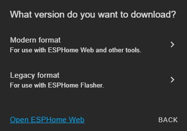
You will be presented with some options for how you want to install the .bin file to your device:
Wirelessly: This is not an option for the first initial flash as it requires the device to already be onboarded to your wifi. You can use this option if you first prepared the device and flashed it when creating the initial node, but this option is primarily used for uploading updates or changes to your configuration file after the initial flash.
Plug into this computer: This means that the device to be flashed is plugged into the computer that you are using to access Home Assistant/ESPHome. This option will compile a temporary .bin file and open up the ESPHome web installers for installation. The temporary .bin file is deleted(?) after the installation. Personally, I like to have local copies of the .bin file as a backup if I even need to restore a device to a previous version after an update, so I do a manual download (see below) then return to this option after the file is downloaded.

Also note that if you are not accessing ESPHome over HTTPS:, you will have to do a manual download anyway. So, if you opt to manually download or are required to because you aren't connected using HTTPS:, follow the manual download steps below then return to this option and select #2: Open ESPHome Web and follow the steps below for the ESPHome Web Installer.
Plug into the computer running ESPHome Dashboard: This means your device is plugged into the box running Home Assistant. This could be your Raspberry Pi, a VM, etc. You aren't likely to use this method and trying to pass through the USB device could cause issues depending upon your Home Assistant setup.
Manual download: This option is used if you want to save a local copy of the .bin file or if the second option isn't using HTTPS.

The configuration file will be compiled. Note that if this is the first time your ESPHome node has been compiled, this could take a few minutes so be a bit patient. If the program compiles without error, the final line in the in the compilation window will say "Successfully compiled program" and you will be prompted to save the compiled .bin file. Save the file and remember the location.
You will now need to restart the installation process, select the second option to 'Plug into this computer' and select the second option "2. Open ESPHome Web" (you do not need to wait for it to try to compile a temporary version again).
The ESPHome Web Installer

If you haven't yet connected your device to the computer's USB port and placed it into flashing mode, do so at this time per the steps above. Then click the Connect link.

You should see your USB-to-TTL adapter listed (I'm using the CP2102 above). Select that option/serial port and click connect.

If communication is successfully established, you will see the above dialog with "connected" displayed in the upper right corner. You now want to select the "Install" option, which will allow us to upload and flash our downloaded .bin file. Even though this is the first time we are flashing this device, you don't want to select the 'Prepare for first use' option. This just flashes a basic configuration to the device and puts it online. You'd still have to flash your device's configuration file after this step.

Use the Choose File button to browse to and select the .bin file you downloaded in the previous step. Then click the Install button.

The ESPHome web installer will establish communication with your device, erase it and begin installing. This can take anywhere from 1-3 minutes. Just be patient and remain on this same web page until finished.
Potential Flashing Issues
If you get an error when ESPHome tries to connect to your device before the installation begins, it is generally due to one of the four following issues, from most to least likely:
1. The device is not in flashing mode. Unplug the device from the USB port, and try reconnecting again being sure you are holding down any button (or other process necessary) when plugging back into the USB port. Try holding the button down for a second or two after plugging back in before releasing it. If using a GPIO0 pin, assure it is securely connected to ground.
2. You did not "cross" the RX and TX connections between the device and the USB flasher. Remember that RX must connect to TX and vice versa. Check your wiring.
3. You select the wrong COM port when prompted. Verify the COM port that your USB flasher is connected to (use Device Manager or other utility if it is not obvious).
4. The computer you are using does not have the proper USB drivers installed for the USB-to-TTL flasher you are using (e.g. CP2102, FT232RL, etc.). You will need to locate and install the drivers for your machine/operating system. Usually a web search for something like CP2102 USB driver will get you headed in the right direction.
If the installation completes succesfully, you will see the following message.

Click close and you can close the web installer and return to the ESPHome dashboard.

You should see your new device is now online and fully functional! You might have to power cycle your device to take it out of flashing mode first. If you held down a button to put the device into flashing mode, just unplug your flasher from the USB port and plug back in, this time not pressing the button. If you had to install a ground connection to GPIO0, you will need to unplug from USB, remove the connection to GPIO0 and then plug the device back in to USB.
You can optionally click on the logs if you want to see the device info such as MAC address, IP address or see any output from the sensors.
If you disassembled the device, you can reassemble the device (see below). If the device is powered by mains power, it is now safe to plug it into mains power or whatever source is normally used to power the device.
Best of all, the device an all its entities are automatically discovered by Home Assistant. But more about the Home Assistant piece below.
Tasmota
Tasmota is different from ESPHome in the fact that you will first flash a basic version of the firmware to your device, then configure the device via the Tasmota web interface. But the actual flashing process is very similar to ESPHome. And like ESPHome, there is more than one way to accomplish the following. You can download the binary from the Tasmota Github and flash with a desktop tool. But again, what I'm showing here is the method I generally use.
After connecting your device to USB and assuring you've placed it in flashing mode (see above), open up the Tasmota Web Installer (https://tasmota.github.io/install/)

There are many different variants of Tasmota available. But unless you have a special need, you will normally just check the standard Tasmota (in the language of your choice). You then need to select the proper processor. For the Sonoff S31, this is the ESP8266. Then click the connect button.

This brings up the exact same dialog as ESPHome! This is because both installers are using something called ESP Web Tools, which is also why the two processes are so similar. Select the COM port where your USB flasher is attached. If using the CP2102, this should be pretty obvious from the name. Click connect.

Select the option to Install Tasmota. Confirm that you want to erase the device and install Tasmota on the next two screens.

You will get a progress dialog that again looks just like the ESPHome web installation. If you do not see a COM port or the connection process fails, check the Potential Flashing Issues above under ESPHome as the same troubleshooting steps or potential issues exist here.

Once the installation is successfully completed, you can click the next button. The following form should appear.

I've had inconsistent results with this and sometimes it just returns to the initial installation dialog with the only options being to Install Tasmota and Logs & Console. If this happens, dismiss the install dialog box, reset your device to take it out of flashing mode (remove any ground wires from GPIO0 if you had to add them) and reconnect, once again selecting the proper COM port. You should then see the above dialog.
I recommend that you immediately select the option to change WI-FI and enter in your SSID and password. This will avoid the need to use your phone to join to a temporary Tasmota AP to set your wifi credentials.
You can then click 'Visit Device'. This will open the web interface for the device where you now need to configure it.
Configuring Tasmota

The default installation for Tasmota just installs the configuration for "Sonoff Basic". This likely isn't going to be what you need for your device. Tasmota has a plethora of options and settings... way too many for me to cover here. Fortunately the documentation is pretty complete, so I'm going to defer to that for most settings and options and only cover the bare basics here for my Sonoff S31 Lite as an example.
First, you can use the Information button to see some useful information, such as the current MAC and IP address of the device. You may want to note the IP address for when you need to return to the web interface and save yourself the effort of having to find it in your router!
At this point, I would recommend removing all temporary flashing wiring, reassembling the device and connecting it to mains power or whatever source is normally used to power it. I cover this for the S31 below. The reason for doing this now is that the 3.3V power won't be enough to power things like relays, etc. and we won't be able to fully test the configuration. Assuming that has been done, I'll continue with the basic configuration.
Start by clicking the Configuration button.

Tasmota comes with a number of 'pre-defined' modules, which in actuality are really just premade templates. The first place to check is under 'Configure Module' and see if your device is already defined for you.

On the screen, I can drop down the module type list and see if my device is already defined.

The Sonoff S31 is already in the list! If I was using the Sonoff S31 (with power monitoring), I could just select and save this module and all the hardware options, relay, power monitoring, LEDs, etc. would be configured for me. But I'm using the S31 Lite which doesn't have the power monitoring. Now, the standard Sonoff S31 would probably work, but I would have a couple of sensors that would eventually show up in Home Assistant that would not be present, giving me an 'unknown' or 'unavailable' entity. The good news is that I can use the Sonoff S31 template as a model for creating one for the Sonoff S31 Lite.
And this is where the Tasmota Device Repository comes in handy. If I look at the configuration information for both the Sonoff S31 and the S31 Lite:

Looking at the GPIO pins, the S31 has an energy sensor that uses GPIO01 and GPIO3 that the S31 Lite lacks. Otherwise, all the other GPIO pins are the same. This means I can use the S31 as a 'template' starting point to create one for the S31 Lite.

To do this, select Configure Template from the main menu.

On the Configure Template screen, I can give my template a unique name and then say I want to base my template on the Sonoff S31. This will auto-fill all the GPIO pins for the Sonoff S31. Since the only difference between the S31 and S31 Lite are GPIO01 and GPIO03, I just need to set these GPIO pins to 'None'.

When I save this new template, it will be uploaded to the device and it will reboot. After the reboot is complete, the main menu will reappear and the device hardware should now be configured and my new template name should be listed.

If the device is plugged into mains power, I can now toggle the relay off and on with the toggle button. Any LEDs should also light or go dark accordingly. If your device has other controls, like multiple relays, brightness or color for something like a light, you should see controls for those hardware options as well.
Note this is only one way to define your device's hardware. I could have just as easily used a generic starting template and manually set all the GPIO pins per the device listing. Or, I could use the 'Configure Other' option to copy and paste a template from the device repository into a template and activate it.

There are a ton of other options to explore that you may wish to consider for your device and particular situation, such as PowerOnState, Device power cycle reset, etc. Again, refer to the excellent Tasmota documentation for much more information on how to use Tasmota with your device.
But there is one more thing that needs to be covered here to use the new device in Home Assistant and that is MQTT configuration. This is because Tasmota uses MQTT to talk to Home Assistant. And this is true whether you are using the Tasmota integration in Home Assistant or manually creating your entities in YAML. The following assumes you already have an MQTT broker setup, or have configured the MQTT add-on in Home Assistant (which includes the broker if you don't have one).
MQTT Configuration in Tasmota

To begin, select Configure MQTT from the main Tasmota menu.

On this page, you need to provide the following information for your MQTT broker:
- IP address or host name
- Port (if different from the default 1883)
- MQTT broker user name
- MQTT broker password
- A unique MQTT topic for this device
Then save your changes.
Next, you need to configure a couple of items that will impact how your device appears and is named in Home Assistant. These can be found under 'Configure Other' on the main menu.

This is from the Tasmota web site and shows how the template name, device name and friendly name will be used when the entities are created in Home Assistant (if using the Tasmota integration). See the Tasmota web site section on Home Assistant for more information on the Home Assistant Tasmota integration and other settings that may be of interest.
Reassemble the device
After your device is flashed, remove any temporary wires you may have attached for flashing. Again, do not connect your device to mains power until all added wiring or jig connections have been removed and the device reassembled.
Reassembly is generally just in the reverse order of disassembly and once again I'll use the Sonoff S31 as an example.

Begin by inserting the main unit into the housing. It only fits one way, but make sure it is firmly seated in the housing.

Replace the three screws. Tighten securely so that the head of each screw is recessed into the screw hole, but be careful not to strip the screw head. Use an appropriately sized screwdriver.

Slide the rails on both sides. The rails are interchangeable, but only fit one way.

Snap the plastic end cap back onto the unit. Note that there is a 'top' and 'bottom' to the end cap.

The small tabs on one edge of the end cap should be on the same side of the housing as the electrical prongs. In addition, when looking at the power symbol on the end cap, it should be pointed "up" once the cap is installed.

It should not take an unusual amount of pressure to snap the end cap back on. Once aligned properly, it easily snaps into place. Don't force it or you risk breaking the retaining tabs on the cap.
Once completely reassembled, you can plug the device into mains power. The end cap button can still be manually pressed to toggle the relay off and on. But with custom firmware installed, it can now be used in Home Assistant for automations.
Home Assistant Integration and Entities
Once powered up normally after flashing, the new notification will show up in Home Assistant. This happens immediately if you have flashed ESPHome and after you have configured MQTT in Tasmota if you have the Tasmota integration installed (if you don't have the Tasmota integration, it can easily be added through the Settings => Integrations menu in Home Assistant).

If you click on the notification on the bottom of the sidebar menu in Home Assistant, you will see that a new device has been discovered automatically.

Under your notifications, click "Check it out" to open the integrations page.

You will see your newly discovered device listed. In this example, I'm showing the ESPHome version, but the Tasmota version is exactly the same. Click the configure button to add it to Home Assistant.

 |
| Click to enlarge |
If you want to see the entities, you can go to Developer Tools => States and filter by your device name (kiosk-power in my case). The above shows the entities created via my ESPHome configuration, but Tasmota would be very similar. Of course the names of the entities are dependent on what you entered in the ESPHome configuration or in the device and friendly name fields in Tasmota.
You can test the relay right from the screen by clicking the small circled "i" for the relay.

You can click this slider to toggle the device off and on. If using the Sonoff S31 or S31 Lite, you should hear the relay click and see the power LED turn off or on. And of course anything plugged into the S31 will receive power as well.
You are now ready to add any of the entities to your dashboards or use them in automations.
Example Automation Use
In the video version of this project, I use my ESPHome-flashed smart plug to control the charging of my Home Assistant Kiosk tablet.

My previous tablet was left connected to power 24/7 and after a couple of years, this caused the Li ion batteries to swell and resulted in a warped back plate that separated from the front bezel.

Luckily I caught this before the batteries exploded (and potentially caught fire). Using my new ESPHome-flashed smart plug, I'm going to keep the batteries on my new tablet between 20%-80% of their charge... which is what is commonly (but arguably) recommended for best battery life.
Now, there are many ways to do this and you don't necessarily need a custom-flashed smart outlet to do the same thing. If you have a Zigbee network, you could use a Zigbee smart outlet without flashing custom firmware to do the same thing. Or you could use a standard cloud-based outlet, as long as it has a Home Assistant integration. This is just one example of how you might use a custom-flashed smart outlet (or other device). The charger for the tablet is plugged into the smart plug, which will controlled by Home Assistant.
This is one other requirement for this automation... and that is a way to monitor the battery charge on the tablet. This is easily accomplished by installing the Home Assistant Companion (mobile) app onto the table. The Home Assistant Companion app has versions for both Android and iOS. While I won't be using the companion app for my display (I'm just using the Chrome browser with a specially designed dashboard), having the companion app installed will return battery percentage, charging status and a number of other stats into Home Assistant.

This, along with the switch entity that controls the S31 relay, is all that is needed to create this simple automation.
While I will be showing the YAML here, these automations can very easily be created via the automation UI in Home Assistant. If you need some guidance on how to translate a yaml automation to the UI version, I have another video that you might find helpful: Recreating a YAML automation using the Home Assistant UI.
Input Boolean (Toggle Helper)
This is optional, but I like to include an input boolean (called a toggle helper in the UI) that gives me a simple slider on the dashboard where I can disable the automations for charging the tablet should I need to do so for some reason.

By toggling this slider, I can override the automations and control the charging manually through the switch, physical button on the device, etc. The YAML for the input boolean is quite simple:
input_boolean:
kiosk_auto_charge:
name: Kiosk Auto Charge
icon: mdi:power-plug
Again, using the UI to create a toggle helper is just as simple:

With that, there will be two automations: One to turn the power/charging on when the battery drops below 20% and another to turn the power/charging back off when battery level exceeds 80%. Obviously, these automations use my entity names and you would need to update your versions to use the name of your entities.
Turn charging on when battery drops below 20%
- alias: 'Kiosk Tablet Charging On'
trigger:
platform: numeric_state
entity_id: sensor.galaxy_kiosk_battery_level
below: 20
for: '00:05:00'
condition:
condition: state
entity_id: input_boolean.kiosk_auto_charge
state: "on"
action:
service: switch.turn_on
target:
entity_id: switch.kiosk_power_relay
This is a pretty simple automation, but I'll describe the highlights in case you aren't familiar with YAML automations.
The automation watches the battery level of the kiosk. When the numeric state of the battery drops below 20 for a minimum of five minutes, it checks to see if the auto-charge input boolean (toggle helper) is enabled.
If so, then it simply turns on the Sonoff S31 to begin charging the tablet.
Turn charging off when battery exceeds 80%
- alias: 'Kiosk Tablet Charging Off'
trigger:
platform: numeric_state
entity_id: sensor.galaxy_kiosk_battery_level
above: 80
for: '00:05:00'
condition:
condition: state
entity_id: input_boolean.kiosk_auto_charge
state: "on"
action:
service: switch.turn_off
target:
entity_id: switch.kiosk_power_relay
Very similar to the first automation, this one watches for when the battery numeric state exceeds 80 for at least five minutes. It once again checks that auto-charging is enabled and if so, simply turns off the Sonoff S31, stopping the charging.
This will keep the battery level of the tablet between 20-80% (well, technically 19-81% since the bounds must be exceeded), assuring the battery is never completely drained nor overcharged or constantly maintained at 100%.
Conclusions and Thoughts
While this article shows the process for flashing custom firmware to a Sonoff S31 smart plug, this same process can be used on many different brands and different types of devices, such as light switches and dimmers, relays, lights and LEDs and even some appliances like air filters, aroma diffusers, fans, etc. Check those device repositories for some additional ideas.
While flashing custom firmware might seem a bit daunting at first, once you've done it the first time, flashing additional devices is much easier (especially if you create yourself a jig or custom wiring harness just for this purpose). However, if you just don't feel comfortable disassembling a device and attempting to flash it yourself, but like the idea of local firmware like ESPHome or Tasmota, some manufacturers have started to recognize the Home Assistant/DIY market and sell smart devices already pre-flashed with ESPHome or Tasmota. Here are a few examples if you are interested (disclaimer: I have not purchased nor tried any of the pre-flashed products myself, so your mileage may vary):
Athom (pre-flashed ESPHome, Tasmota, WLED and more)
CloudFree (primarily Tasmota)
Martin Jerry (primarily Tasmota)
Of course with the growth of Zigbee, and if you have a Zigbee network already setup and integrated into Home Assistant, many of these same devices have Zigbee versions, that by nature are already completely local and do not require any flashing. Z-Wave is another option. And of course, if Matter ever makes its way into the mainstream (and avoids major fracturing), this may further eliminate the need for custom firmware to get complete local control. But the outcome of Matter is still very much in doubt at the time of this article.
Let me know your thoughts or ideas down in the video comments. And thanks for reading!
Links and Additional Info
If you'd like to support future content on this blog and the related YouTube channel, or just say thanks for something that helped you out, you can say thanks by buying me a one-off cup of coffee at:
No comments:
Post a Comment
To help eliminate spam and to keep all conversations civil, submitted comments are moderated. Therefore your post may not show up immediately. Please be patient as most reviews are completed within a few hours.