

It is quick and easy to add some peripherals to your WLED controller and projects. Why would you want to do this when WLED has a web interface, mobile app and can also be controlled by automation systems like Home Assistant? Well, sometimes you can't beat the convenience of a nearby local pushbutton to do something like turn your LEDs on or off, or quickly select a favorite effect or even start a playlist without the needing to use your phone, tablet or computer.
You can also easily add things like a remote control, dimmer control, motion sensors, microphones and even relays to your LED projects. And all this can be done without writing any code or compiling special versions of the WLED firmware.
This article is written in conjunction with the YouTube video that shows step-by-step processes of how to add these components, along with the setup steps required in WLED. You may wish to watch that video then use this article as a reference source when ready to create your own WLED controller.
Prerequisites and Caveats
This article will assume that you have already created a basic WLED controller with a proper power supply and wiring for your LEDs. The voltage and type of LEDs really don't matter as this focuses on adding peripherals to the controller itself. If you have not built your own WLED controller (you really should try it... it's easy!), then I have a number of resources that can help you build your first basic controller:
Videos
How to Quickly Build Your First LED Controller (in 15 minutes with no soldering!)
Build your own LED controller for under $6 with WLED (soldered version)
A Beginner's Guide to DIY LED Projects (general info on LED strips, power, etc.)
Using WS2812b RGB Light Strips (info on using one of the most common LED types)
Written Articles
Standard Wiring Diagrams (various diagrams for different LED strips and controllers)
Building your own LED Controller (companion article to above video)
RGB LED Strips - A Beginner's Guide (companion article to above video)
Planning an LED Installation (general information)
The controller that I will be referencing for all these components is just running the latest standard production version of WLED (0.14.1 as of publication date).

The only exception is that I opted to include the Audioreactive add-on so that I can connect different microphones for sound reactive effects. Note that the Audioreactive add-on is only available if you are using an ESP32 board as sound reactivity isn't supported on ESP8266 boards.
ESP8266 vs. ESP32
Most of the options included in this article, except for microphones/audio reactivity, will work with both ESP8266 and ESP32 boards. Any other exceptions will be noted under the particular peripheral.
For this article (and related video), I will be using a standard ESP32-VROOM-32 NodeMCU style board. If you are using a different board, you just need to map your GPIO pins accordingly (see next section). Also note that the ESP32 now comes is various versions (e.g. C series, S series, H series) and not all of these will be able to run WLED. You generally need a dual-core board with WiFi. You can see the WLED site of fully supported controller types.
GPIO Pin Selection
For many peripherals, WLED will let you specify which GPIO pin(s) you are using. This means you have a lot of flexibility in terms of the the pins that are available and that you opt to use on your controller. But not all GPIO pins are created equal!
Some GPIO pins have special uses or can even prevent your board from booting if connected to the wrong peripheral. A really good source that I routinely use for checking out which GPIO pins are safe to use comes from Random Nerd Tutorials.
 |
| D1 Mini ESP8266 Pinout |
 |
| ESP8266 Pins and Uses |
Also note that not all development boards break out the same GPIO pins, especially on ESP32 boards. You will just need to find an appropriate pin and substitute from my diagrams below. I'll try to note any "gotchas" under each peripheral type.
Mixing and Matching Peripherals
In most cases, you can mix and match many of these peripherals to meet your particular project needs. There are a handful of exceptions, such as using an IR receiver with a microphone/audio-reactivity, can have issues. I'll try to note any of these below, but as of WLED release 0.14.1, you can theoretically add:
- Up to four "buttons" (two on the ESP8266) for binary sensors, including analog sources like a potentiometer and touch control.
- IR receiver for remote control
- Relay
- Microphone
Important Note: Always remove power from your controller before adding or removing any peripherals!
Wiring Diagrams Shown
For most of my wiring diagrams, I'll be showing direct connections to the GPIO pins on the ESP controller for each individual component type. Naturally you can create these same connections via breadboard, prototype board or PCB. When connecting multiple peripherals that may require voltage and/or ground connections, creating a power rail with voltage (5V and/or 3.3V) and ground on something like a breadboard or proto board may be necessary, as your ESP board may not have enough of the 3.3V/5V or ground pins available. I'll show an example of this at the end of this article.
Parts Used or Shown
The list below contains the parts I used for this article and the related video. Obviously many of the items can be substituted. A normally-open pushbutton is pretty much the same regardless of the form factor or packaging. However, I do want to make a note about the ESP32. I am using a standard 30-pin ESP32-VROOM-32 (it's what I already had on-hand). Note that this particular model isn't really breadboard friendly as it is just slightly too wide to leave a row for pin connections on each side (and hence I'm using a protoboard). But you can use a 38-pin narrow version that is breadboard friendly if you plan on using your ESP on a standard breadboard or something like an ElectroCookie board. So I'll leave a link to the narrow version as well.
Also note that all components are not created equal! For things like the ESP32, there are a lot of clones or 'cheap' versions that cut corners by using things like a cheaper power regulator. I'm linking to parts that I actually used.. but even that isn't a guarantee of future reliability, as some of the parts I used were purchased quite some time ago.
|
PART |
Notes/Comments |
|
Not breadboard
friendly due to width |
|
|
Will work on standard
breadboard |
|
|
Optional but
recommended |
|
|
Any addressable LEDs can be used |
|
|
Normal closed can
work as well |
|
|
This one rated for 12v, but any SPST switch works |
|
|
|
|
|
Adjustable time period |
|
|
Adjustable time period |
|
|
|
|
|
Other values can be
used ≥10 kΩ |
|
|
|
|
|
|
|
|
|
|
|
|
|
|
|
|
|
|
|
|
Should be sized
appropriately for your LEDs/project |
|
|
|
|
|
|
|
|
A standard 30-pin
ESP32 will work on this board |
|
|
|
|
|
|
|
|
|
|
Some of these links may be Amazon affiliate links. Use of these links will not affect your pricing, but as an affiliate this channel may earn a small commission if you make a purchase.
Adding Simple Pushbuttons
Adding a pushbutton is one of the easiest, yet most useful peripherals you can add to your WLED controller. Each button can have three separate functions defined... single press, double-press and long press. This means that each button can do three different things. The current version of WLED had four buttons "slots" for the ESP32, meaning you could technically add twelve different functions, all accessible via pushbuttons. Note that the ESP8266 version only supports two button slots and while the functionality is the same, I'll be referring to the ESP32 version moving forward. But in most cases, you'll only need one button.
Wiring

You should use a normally-open, non-latching push button. It is possible to use a normally-closed button and invert the selection in WLED, but use caution when selecting the GPIO pin because some pins could result in a boot failure if the pin is pulled high or low. See the info on GPIO pins above. You'll connect one side of the push button to ground (GND) and the other to an appropriate GPIO pin. I'm using GPIO18 for this example.
WLED Configuration
Once you've connected your first button and noted the GPIO pin in use, you can power up the controller and open the WLED web page.
From the Config menu, select the option for LED Preferences (this is actually the LED and Hardware Setup page) and scroll down to the section where the four button slots (or two for the ESP8266) are listed.

You can select any of the four button slots for your first button.

Simply select the GPIO pin that you used for the button and a type of pushbutton. If you used a normally-closed button, you can select 'push inverted' for the type and WLED will reverse or invert the button operation.
If the GPIO pin you used for the button is not shown in the drop down or is grayed out and unavailable for selection, it means that the GPIO pin isn't appropriate for the type of device connected (e.g. an analog pin for a digital connection) or the GPIO pin is already in use. For example, if you built a standard controller and used GPIO16 for your LED data line then GPIO16 will be grayed out and disabled for selection.
Special Notes for Button 0
Button 0 has a few special features. For one, it has a default action for the single (short) press that will toggle your LEDs off/on. A long press will select a random color for your LEDs. But a long press of >6 seconds will actually reset the WiFi and cause the controller to begin broadcasting the WLED hotspot again. And a long press of >12 seconds will erase the flash... meaning WLED would need to be installed again. Please note this if installing the button in a location where someone may inadvertently hold the button down for an extended time, like in a small child's room. In this situation, you may wish to use one of the other three button slots for your pushbutton.
For the other three button slots, when a pushbutton (or push inverted) is selected, the default actions are single press will cycle through the effects, long press will ramp up brightness and a double-press will cycle the color palettes.
But what if you want your button to do something other than the default action? No problem, you can assign the button actions to 'presets' that you also define in WLED.
WLED Presets and Macros
WLED supports up to 250 presets that can be used to save a state and be easily recalled via shortcuts in the WLED interface or through the action of a peripheral such as a button press.

Note that each preset has a unique number assigned, along with a custom name you can define for that preset. We'll use these numbers to assign an action to something like a button press below.

When you create a new preset you give it whatever name you like. By default it is configured to save the 'current state' of the LEDs. So this would be things like the current effect, speed, color palette, etc. You can also save the current brightness and segments if you are using them. Each preset also gets a unique number (this is what we will use in our actions). Once saved, this preset is available to select from the WLED main page or through macro actions. But there's more than just saving a state available via the presets.

If you uncheck the box to 'Use Current State' when creating a preset, you are now presented with an API command box where you can enter commands to controls your LEDs and controller. The above example, for instance, will cycle through presets 1-6 each time the preset is called. With this, we can now assign a button press to preset 102 and each time the button is pressed, it will cycle through presets 1-6. This is just a simple example. A full description of all the various commands is beyond the scope of this article (and note that you can use JSON for even more control). You can find a full list of available commands on the WLED web site. The important thing to note here is that we can create presets that save the state of the LEDs (effects, colors, etc.) or presets that will run commands. These are what we will use for our peripheral actions.
Assign an Action to a Preset
Once you have created the desired presets, we can assign those to actions, such as button presses. To do this, go to Config, then select Time & Macros.

Note that a value of zero for any of the actions means that the default action, if any, will be used. In the case of button 0, the default action for a short press is to toggle the LEDs off/on. We'll leave that as the default. But for the long and double press, we will assign presets (custom actions). Using the example presets above, a long press will now set the LEDs to 'Colts Pregame' which has a particular color, effect, etc. But for the double-press, the preset 102 will be used, which contains the command to cycle between presets 1-6 each time the button is double-pressed. So with this one button, we can turn the LEDs off/on, quickly select the Colts Pregame effect or cycle through different presets. And there is a TON more that can be done with WLED commands. This is just a very simple example.
But what if three commands/presets aren't enough? Well, simply add another button!

You can connect a second button to different GPIO pin (19 in my example) and configure the next button (e.g. Button1) with the selected GPIO and pushbutton as the type (just like the first one).

Let's move on to other optional peripherals.
Adding a Switch
A switch is very similar to a button, except that when toggled on, it remains in that state instead of returning to the original state like a push button.
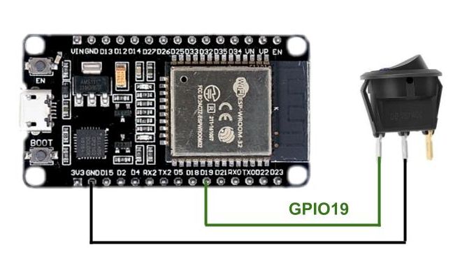
A switch is wired just like the pushbutton... with a connection to an appropriate GPIO pin and ground. Some switches may have a third (or even fourth) terminal. Normally these are used to either provide power to an onboard indicator light or to change how you want the switch to operate. In most cases, you want to select the two terminals that are connected when the switch is in one position and disconnected in the other. Use a continuity tester if unsure.
Once wired, again return to Config / LED Preferences to define the switch.

The setup is almost identical to the pushbutton, where you select the GPIO pin where your switch is connected. But this time you select switch as the type.
The default actions for the switch is to toggle the lights off/on. But like buttons, you can define custom actions for the switch under Time & Macros.

Again, a zero indicates the default action (toggle off/on), but note that a switch only has two actions available... when the switch is turned from on to off, and when it is turned from off to on. There is no double-press action available for switches. But if you wish for your LEDs/controller to do something other than toggle off/on when the switch is flipped (like maybe go from low to high brightness?), you can specify your own preset here.
PIR/Motion Sensors
PIR or motion sensors are also configured as 'buttons' but offer two different setup option. Wiring is similar to a button or switch, but the PIR sensor also requires power.
 |
| Click to enlarge |
Note that most common PIR sensors like the AM312 shown above will operate off of 3.3V or 5V. But check the documentation for your particular sensor, noting that the polarity/pin out may not be the same as the image above. But you will connect the sensor to the appropriate voltage and ground and the data pin to an appropriate digital GPIO pin. Once wired, you will configure the sensor in a button slot under Config / LED preferences. But you have two options in this case.
Configuring as a switch

When configured as a switch, the PIR sensor will function just like the switch above, with the default action of turning on the LEDs when motion is detected and turning them back off when motion ceases and the sensor resets. Note that this means the LEDs will remain on for different times depending upon the cooldown period of the sensor. This can be as short as a few seconds or as long as a minute or more. To have better control over the time, a PIR sensor like the HC-SR501 (or even something like a microwave sensor) that has an adjustable cooldown period could be used.
Configuring as a PIR Sensor

If configured as a PIR sensor, then the buttons actions can be used to run launch a different preset when motion is triggered and when it clears. This can give you a bit more control over what happens related to motion.

Note that it is also possible to use multiple PIR sensors. One could be used to turn the LEDs on and set a certain effect (but not turn them off when cleared) and the other motion detector could be set to turn the LEDs off with motion... or set a different effect. Between the two sensors, presets and macros, you can do some pretty fancy stuff! But do note that WLED doesn't have a true automation engine (yet), so some things may require an outside system like Home Assistant for true automation. But do note that Home Assistant has a native integration and you can completely manage the controller and LEDs from Home Assistant, including launching presets.
See the section on Using PIR Sensors on the official WLED web site for more information on using motion sensors.
Other Binary Sensors
While buttons and switches may be the most common, you can theoretically connect any binary sensor or device to the WLED controller and configure it for your specific needs. Some examples might include (but certainly aren't limited to) digital light level sensors, wired reed switches, touch controls, etc. As long as it can be connected to a GPIO pin with the appropriate signal (remember that ESP GPIO pins are only 3.3V tolerant), you can configure and use it as a switch or button in WLED.
Analog Buttons (Potentiometers)
There is one final options for the "button" types in WLED that I'm going to cover... and this is an analog button. An analog button is one where the voltage to an analog pin will be varied via resistance... basically we are talking about a potentiometer. This varying voltage can be used to control things like the brightness of the LEDs, the speed of an effect, etc.

For the wiring, you will connect a 10kΩ (or greater) potentiometer's fixed pins to 3.3V (do not use 5V!) and ground. The variable output will connect to an analog (ADC) capable pin on the ESP board. If using an ESP8266, there is only one ADC pin labeled A0. But if using an ESP32, there can be up to 18 ADC pins available, normally broken out into two groups of ADC1 and ADC2. You must choose a GPIO pin that is part of the ADC1 group!

ADC2 cannot be used while WiFi is also in use. In my example, I'm using GPIO34, which is ADC1 channel 6. The channel is insignificant, but ADC1 is not!
Once wired and the controller is powered back on, you need to first define the button under LED Preferences.

In an unused button "slot", select the GPIO pin used (note that some pins are marked as R/O - read only - meaning they are input only pins) and set the type to analog. After saving, we need to go to Time and Macros to set which function we want to control with the potentiometer.

For an analog button, set the short and long actions to zero and the double action to one of the following values depending on what you want the potentiometer to control:

In my example above, I have the action set to brightness. I can now turn the knob on the potentiometer to control the brightness of my LEDs! You can change the value to control other settings but note that not all effects have all settings. For example, the solid color effect doesn't have a speed setting. If an effect is in use that doesn't have an option, then turning the potentiometer will have no impact on that effect.
In addition, you can adjust the range/sensitivity of the potentiometer by selecting a different Ω value or by adding an additional resistor as shown above. Note that when using global brightness WLED will, by default, turn off the LEDs at each extreme end of the potentiometer (0V and 3.3V). Adding a resistor can override this behavior. See the information on Analog Buttons on the WLED web site for more info and proper selection of a resistor based on the potentiometer.
If you find that your potentiometer is working "backwards" (e.g. the brightness goes up when you turn the knob "down" or vice versa), you can either reverse the +V/GND connections on the potentiometer or change the button type to Analog Inverted in the button definition.
Note: You cannot connect an analog button and also an analog microphone for audio-reactivity at the same time. However you can use a digital microphone with analog buttons. See the section on microphones below.
OK.. that covers the buttons types. Note that you can mix and match any of the above options, up to four different button types (based on current release... the number is lower in older versions and may change with future versions).
Let's move on to other types of peripherals now.
IR Remotes
By adding a simple, low cost IR receiver to your controller, you can use a remote to control your LEDs from across the room! WLED has support for a number of pre-defined remotes, but also supports defining your own via JSON so you can make nearly any IR remote work.

Most IR receivers will work with 3.3V or 5V. But check the documentation on your component and also verify the pinout, as yours may be different than the one I show above. But as a general rule, you will connect +V and GND then the data/out line to an appropriate digital GPIO pin. I'm using GPIO4. Once connected and the controller is powered back on, return to the Config / LED Preferences to configure the IR remote.

Just under the button settings, you will see the IR setup. Simply define the GPIO pin you are using, then select the actual remote control you will be using. For most of my installs, I use this 44-button RGB remote (a link to this remote can be found in the parts list above):

It allows me to toggle the LEDs off/on, control brightness, select colors, presets and more. But a number of other remotes have built-in support in WLED:

In addition to these preconfigured remotes, it is possible to modify or even add your own remote via the JSON remote option. If you know (or can obtain) the codes for your remote, you can create a JSON file to have it control WLED. You can also modify any of the existing preconfigured remotes for different functionality in this same manner.
To see a list of all the preconfigured remotes, along with information on creating or modifying the JSON remote file, see the Infrared page on the WLED site.
Note: There are currently known issues when attempting to use an IR remote simultaneously with a microphone/audio-reactivity. I did not experience issues in my test build for the video when using IR with a digital microphone, but if you have issues with the remote when a microphone or audio-reactivity is enabled, you may have to disable the remote or choose between remote control or audio-reactivity until these issues are resolved.
Microphones
Currently, audio-reactivity is still considered a "user mod" for WLED. However, it is offered as and option for the standard installation so customization and compilation of your own firmware isn't necessary.

There are also forks and development versions of WLED (Sound Reactive, Moon Modules, etc.) that support audio-reactivity. But I'm sticking to the production releases of normal WLED at this point. I only mention the user mod issue because it is under that area of the configuration where we will configure the microphone and enable the audio-reactivity of the controller.
Note: Audio-reactivity is currently only available for the ESP32. It is the only peripheral option on this list that is not available for the ESP8266.
Note: You cannot connect both an analog mic and an analog button (potentiometer) simultaneously. However, you can use a digital mic and analog button at the same time.
For microphones, WLED supports both analog and digital microphones. A digital microphone is strongly recommended as it will provide much better responsiveness. But I'll include wiring and setup information for both types.
Analog Microphone (MAX9814)

To connect the MAX9814 analog mic, wire 3.3V to both VDD and GAIN. Connect GND to ground and Out to any of the available ADC1 channels on the ESP32. You cannot use any of the ADC2 channels because these channels are not available when also using WiFi. If you are using a different analog mic, check your device's pinouts, but the line out should still be connected to one of the ADC1 GPIO pins (GPIO32 - 39).
To define and configure the microphone, you must go to Config / User Mods.

If you do not see an AudioReactive section under the User Mods menu, then you did not opt to install the audioreactive add-on during initial WLED installation. You can reinstall WLED, but note that doing so will erase all current settings, presets, etc.
If you do have the Audio Reactive mod installed, then you simply need to check the box to enable it and select the GPIO pin that your mic is connected to... and you must select Generic Analog under the digital mic setting. This took me quite a bit of time to discover and I could not figure out why my analog mic would not work. After saving these settings, you must reboot the controller for it to take effect.
If after rebooting and your LEDs do not seem to react to sound when selecting an audio-reactive effect (see below), then you may need to adjust the squelch, gain and/or AGC. These can be found on the User Mod page, right below the mic settings.

I've found that when using analog microphones, constant adjustments to these values are necessary based on the type of sound source (e.g. heavy bass vs. heavy vocals) and often even when a different effect is selected. It can be frustrating to try to find the right balance.
Digital Microphone (INMP441)
You will get much better and consistent response when using a digital mic, despite the extra wiring required.
 |
| Click to enlarge |
This particular digital mic does require 3 GPIO pins, plus two ground connections and 3.3V. Once wired and you power up the controller, you go to the same User Mod page under Config to define and setup the microphone.

Again, assure that AudioReactivity is enabled. If you previously had an analog microphone connected, be sure to set the pin for this back to unused. For the INMP441, you should select Generic I2S as the type. If you are using an different style, select the type to match your mic from the dropdown list.
Set the SD, WS and SCK GPIO pins according to how you wired the mic to your controller. For the INMP441, the MCLK pin isn't used, so leave this as 'unused'. After you save your changes, it is necessary to reboot the controller before the audio-reactivity will be enabled.
Sound Reactive Effects
Not every effect in WLED will react to sound. However, those that are audio-reactive are noted with a musical symbol and you can use the filter under the list of effects to select only sound reactive effects.

Those effects marked with (♪) react to volume only, while those effects marked with (♫) react to frequency. Those without either symbol are non-sound reactive effects. Note that many of the frequency effects have slider controls to tweak the response. There are also general settings for gain, squelch and other frequency settings on the User Mod page. More information can be found on the WLED web site.
Relays
WLED also allows connection of a relay. The most common use case is to completely kill the power to the LEDs when they are turned off via the controller. Even when the LEDs are "off", they still continue to draw a small amount of power, reportedly around 1W per 300 LEDs, but I did not test this. By installing a relay, you can apply power to the LEDs when turned on via WLED and completely shut off the power to the LEDs when turned off via WLED, without also killing power to the controller. There are many other uses for relays as well.
Power Requirements
To trigger the relay from a GPIO pin without boosting the voltage, you will need to use a 3 or 3.3V relay. Note this has nothing to do with the voltage being switched off or on.. just the power required to signal and energize the relay.

As you can see in the above picture, this particular relay needs 3V to trigger and energize the relay, but it can handled switched loads of up to 30VDC @ 10A. So this relay can be triggered using a 3.3V GPIO pin, but can switch 5V, 12V and 24V LEDs off/on. Just be sure your LEDs don't exceed the 10A max.
But the other factor here is the current (amps) required to energize the relay. The specs for this particular relay says the 'working current' (current needed to energize the relay) is 65mA.

But when I actually measured the current draw to energize the relay, I found it to be closer to 73 mA. This can be important if you actually want to power the relay from the 3.3V pin and ground on the ESP board.
 |
| Powering relay via the onboard 3.3V pin |
The amount of current that can be drawn from the 3.3V pin will depend upon the onboard power regulator of your ESP board. Quality regulators can handle up to 600 mA, but many clones or "cheap" ESP boards may use a lower quality regulator that can't handle the higher current levels. This can cause brownouts, random reboots, the relay failing to stay energized and in some cases can even damage or destroy your ESP board. And remember that the ESP chip itself is also using 3.3V power, along with any other 3.3V peripherals. It would be quite easy to exceed the max current. If you are experiencing issues with the relay energizing, or staying energized, or if your ESP seems to be misbehaving or rebooting, it may be necessary to power the relay from the main power supply and step down the voltage using a buck converter.

In this diagram, the primary power supply (5V, 12V or 24V) that is powering your LEDs can be used to directly provide power to energize the relay instead of using the ESP onboard 3.3V. You just need to install a buck converter that can handle the incoming voltage and step it down to the 3-3.3V required by the relay. This is the safest option for using a relay, but you may be able to wire it directly to the 3.3V pins of the ESP board depending upon a number of factors... including the power regulator, current draw of the relay, etc. Your mileage may vary, but be forewarned that drawing too much current from the ESP board may cause issues or even destroy the board (this is also the same reason you shouldn't power more than just a handful of LEDs directly from the ESP board).
Regardless of how you wire the relay, you will use a single digital GPIO pin to control when the relay is energized. In my example, this is GPIO12. Once wired, power on the controller and once again go to Config / LED Preferences.

You'll find the relay setting directly underneath the button setup. Simply select the GPIO pin you are using. Whether you check the 'Invert box will depend on how you wired up the load (e.g. LEDs) and how you want the relay to function in relation to the WLED power button.

To kill power to the LEDs when you set the LEDs to off in WLED, then connect the LEDs to NO and check the invert box. If you used the NC terminal or find that the relay is operating opposite of how you want, simply clear the invert box.
While controlling power to the LED strips are the most common use, you can use the power state of WLED (off/on) to control power to multiple other devices... as long as the relay supports the voltage/amps of the device to be controlled.
Other Peripherals (user mods, forks, etc.)
This is only a list of the default types of components that can be added to standard WLED. There are a multitude of other components, such as sensors, rotary encoders, displays and more that are available via the WLED User Mod repository or through various forks of WLED. But do note that installing user mods currently requires that you download the mod(s) and compile your own WLED firmware using something like the Arduino IDE. Also note that some mods may break other functions on WLED or may not continue to work with future versions of WLED if the original developer does not keep the mod up-to-date.
But if you are comfortable with compiling and using the Arduino IDE, you might check out the user mods and see if there is something useful for your next LED project.
"Franken-Controller" Example (all components!)
As a final example, I wanted to show the wiring for the example I used in the video to show how multiple peripherals can all be connected and used simultaneously . Now, you'll probably never want a controller with all these simultaneous options (some of which are even kinda' contradictory to each other), but it just serves as an example of all the various components than can be connected.
 |
| Click to enlarge |
This controller has a push button, a switch, a PIR motion detector, a dimmer (via potentiometer), an IR receiver for remote control, a digital microphone for sound reactivity and a relay for cutting power to the LEDs... all connected to a single ESP32 running WLED! Since I was using a buck converter to power my relay, I opted to create a 3.3V rail from the buck converter output since it can handle up to 3A (significantly more than the 3.3V pin on the ESP). But if you aren't using a relay with a buck converter, you can create the 3.3V rail from the 3.3V pin and ground on the ESP board.
 |
| Click to enlarge |
Just be sure the total current draw of all your connected components doesn't exceed the max current draw on the 5V or 3.3V pin.
To see this controller in action and how it use with WLED, check out the end of the YouTube video.
As always, thanks for reading and let me know down in the comments if you have any thoughts or questions!
Links and Additional Information
While I enjoy creating and sharing new projects, the process of making videos, writing blog articles and creating Github repositories is a time-consuming endeavor.
If you'd like to support future content on this blog and the related YouTube channel, or just say thanks for something that helped you out, you can add your support by buying me a one-off cup of coffee at:
No comments:
Post a Comment
To help eliminate spam and to keep all conversations civil, submitted comments are moderated. Therefore your post may not show up immediately. Please be patient as most reviews are completed within a few hours.