

Are you interested in building your own custom LED lighting at a fraction of the cost and with hundreds of more custom effects than in a 'pre-built' version? It's pretty simple to do with just some basic skills.
I did a companion YouTube video on building and using LED strips targeted towards beginners. From that video (and a few others I've done on LED lighting), a number of additional questions have arisen. So this article will repeat a lot of the same information as the video, but will add a few more details and address some of the unanswered questions.
Advantages of DIY
You can buy many different types of pre-built... and pre-programmed... LED strips and displays. While these vary widely in terms of costs and features, you can almost always build-your-own at a fraction of the cost. In addition, you can often get many additional features and options.
Many of the pre-built options may come with a controller similar to this:

This, or the related app, might come with a handful.. or even a couple of dozen.. different effects or scenes. But by building your own controller and using the excellent WLED firmware and app, you can have hundreds of different effects, presets, playlists and more. In addition, you can still add remote control support, local pushbutton control, music or sound reactivity, automation integration and more!
Plus you get the satisfaction of building something yourself... and maybe learning a thing or two along the way. It's really not that difficult and there is a lot of help available online. I'll provide links for some of the items shown in this article at the bottom, so check there if you are interesting in buying anything I show here.
Types of LED Strips
Before beginning any project, you have to determine your desired goals and which type of LED strip might best meet your needs. LED strip lighting comes in more flavors than ice cream at Baskin-Robbins! And they have all sorts of weird acronyms: WS2812b, APA102, SK6812, RGB, RGBWW, 5050, etc. But, while there are some specifics, the types of LED strips boils down to six main categories:
Voltage
This is the DC voltage needed to power the LED lights. The two most common voltages are 5V and 12V, but other voltages are available. As a general rule-of-thumb, the higher the voltage, the more LEDs you can use before you have to worry about power injection (don't worry if you don't know what power injection means... I'll get to that later). 12V or higher is generally best for situations where you might have a lot of LED pixels (a pixel refers to a single LED light within a strip or string) and the limited ability to run additional power to the strips. This might be something like a large outdoor Christmas display. The drawback to 12V pixels is that in most cases, you can only control individual pixel color in groups of three (although there are exceptions). 5V strips are much more common and generally cheaper than their 12V counterparts.
Analog vs. Digital
Analog strips generally only have a single "controller chip" that controls all the LED pixels in the strip. This means the whole strip acts together and can only be set to a single color as a whole. Digital strips have a chip on each pixel (or every 3 pixels for some 12V variants), meaning each pixel or pixel group can be a different color... and this also allows all the various lighting effects. This article will only be discussing the digital variety of chips, as odds are that if you are reading this, you are looking to build something with all sorts of fancy lighting effects!
Clocked vs. Clockless
This has to do with how the LEDs are 'driven'. Clock-less LED strips have the advantage of only needing one data wire, while clocked strips require both a data and timing (clock) signal.. meaning two wires.

RGB vs. RGB + White
RGB obviously stands for Red, Green and Blue. Each pixel in an RGB strip has an independent red, green and blue diode. Controlling the brightness or intensity of each of these diodes give you the various colors. As an aside, most software libraries that control LEDs use a brightness level of 0 (off) to 255 (full brightness) for each diodes level. So to get a color like magenta, the red and blue pixel would be set to full brighntess (255) and the green diode would be off (0). This is normally represented by something like RGB(255, 0, 255). Cyan (blue + green) would be RGB(0, 255, 255). By setting different values for each of the three diodes, a theoretical 16+ million different colors can be generated.
RGB obviously stands for Red, Green and Blue. Each pixel in an RGB strip has an independent red, green and blue diode. Controlling the brightness or intensity of each of these diodes give you the various colors. As an aside, most software libraries that control LEDs use a brightness level of 0 (off) to 255 (full brightness) for each diodes level. So to get a color like magenta, the red and blue pixel would be set to full brighntess (255) and the green diode would be off (0). This is normally represented by something like RGB(255, 0, 255). Cyan (blue + green) would be RGB(0, 255, 255). By setting different values for each of the three diodes, a theoretical 16+ million different colors can be generated.
However, to get white, it means combining all three of the RGB diodes at full brightness - RGB(255, 255, 255). The problem is this doesn't really give a true 'white'. In most cases, the white has a blueish or purplish tint to it. To overcome this, some LED strips add an independent true white diode.... and these are indicated by various designations, such as RGBWW, RGBCW or RGB-CCT. The additional letters indicate the "type" of white... WW (warm white), CW (cool white) or CCT (correlated color temperature) that uses two white diodes to give you a broader range of white between warm and cool. If you are looking for your LEDs to give you a true white for something like task lighting, reading, etc., then adding a true white diode would be advisable. If you are just looking for ambient lighting and cool lighting effects.. and having a true 'white' isn't that critical, stick with just a basic RGB light strip.
Pixel Density
While technically part of the type of pixel, pixel strips also come in various densities, or pixels per meter. The three most common varieties are 30, 60 and 144. This refers to the number of individual pixels per length of the strip.

There are other variations. Obviously, the higher pixel count, the higher the overall brightness. But higher count also means higher power requirements (and more power injection). Also note that the 144/m variation often means a slightly wider strip.. as this extra width is needed for the circuitry. Unless you have need for extra brightness (such as task lighting), 30/m or 60/m are generally acceptable for most other ambient lighting projects.
Many strips also come in white or black, but this is purely aesthetic and has no impact on functionality.
IP Rating
While it technically doesn't impact functionality, strips come in various dust and water-resistant ratings. This is an important consideration, however, if you are going to install your project outdoors or in another damp or dusty location. The most common IP ratings for LED strips are (you can look up the actual IP rating definitions - I'm summarizing as applied to LED strips):
IP30 - Only suitable for dry, indoor installations. No dust or water protection.
IP65* - Protected from dust and water spray. OK for most outdoor installs where not directly exposed to large amounts of water beyond some splashing/spraying.
IP67* - Protected from dust and water. Can be submerged in water up to 1m*.
*Note: There are many other factors in making an LED installation acceptable for outdoor use, including properly sealing all wiring, joins and other items, such as the controller. The above only refer to the strips themselves. I won't be covering water-resistant or water-proof installs in this article.
Other Terms
You may also see terms like SMD 5050 or SMD 3528 with some LED strips. This simply refers to the size of each chip (or pixel) in millimeters. SMD stands for surface mount device. So a 5050 chip is 5mm x 5mm, while a 3528 chip is 3.5mm x 2.8mm. Most RGB LED strips will be SMD 5050.
WS2812b LED Strips
The WS2812b LED strips are a great strip to use for most projects. They are relatively inexpensive and good for beginners. They are 5V, clock-less, RGB, SMD 5050 strip. If you really want true white light, then go for SK6812... which for all intensive purpose of this article, are treated exactly the same except in configuration of the controller software. Many of the items discussed below will work with other strip types, but some adjustments may need to be made (e.g. running two wires from the controller for clocked strips), but the focus will be on WS2812b, 60 pixels/m IP37 rated strips for indoor projects.

Note that as a clock-less strip, there are only three wire connections needed: +5V DC, the data signal and ground. You'll also see that the data line is labeled as DIN (data in) and DO (data out), along with an arrow indicating the data direction.
Data Direction
While DC power can "flow" in either direction and can be added to the strip at any location, the data signal only flows one direction. This is generally indicated on the strip by some sort of arrow. This data direction is something that you will need to carefully note for all your projects. Attempting to connect your controller data line to the 'out' side, or joining two strips together that do not maintain this data flow direction will result in a non-working strip.

Cutting LED Strips
One of the advantages of 5V digital LED strips is that they can be cut to length, anywhere along the strip. This means they can be customized for any given project, controlling not only the length, but the precise number of pixels.
To cut the strip, simply use a good, sharp pair of scissors and cut through the center of any of the sets of copper pads.

You want to leave equal amounts of copper pad on both sides of your cut so that you can attach or solder connections later.
Connecting LED Strips
The LED strips by themselves aren't very useful until you connect some power and a data signal! There may also be situations where you want to turn a 90° corner and need to cut and join various lengths of strips. There are a multitude of ways to make these connections, and each have its pros and cons and will be somewhat dependent upon your comfort level with things like soldering.
JST Connectors
Most LED strips come out of the package with a JST connector added to the start and end of the strip. JST connectors are simple 3 pin (or 4-pin for clocked strips), snap-together joins and can be used to easily attach one strip to another.

As a general rule, the female (or smaller end with the tabs) connector is attached to the data IN side of the LED strip and the male connector to the data OUT end. While this isn't a technical requirement, sticking with the standard will assure you won't end up with a situation where you need to plug two female ends together to maintain the data direction.
As mentioned, most LED strips have a JST connector already attached at the beginning and end of the strip. But you may also see two additional wires (normally red and white) at this connection point:

These extra wires are for injecting extra power into your strip. I'll talk about power injection in a bit, but you generally won't need these wires at the beginning of your strip because you'll already be applying power via the JST connector. Power injection normally happens (and these wires would be used) when connecting multiple strips together.
If you need to attach your own JST connectors (for example when joining partial strips that you've cut), it is very easy to do with some basic soldering.
Just tin and apply a little bit of solder to the three copper pads. Just enough to cover the exposed pad and don't leave the soldering iron in contact with the pad/strip for too long or you risk melting the strip. A little flux might be helpful here, but generally isn't required. The JST connectors normally come tinned already, but if using your own wire, strip and tin a small section of the wiring.

Then just lay the wire over the copper pad and gently push down with your soldering iron to melt the solder and join the wire to the pad. Just be careful and check that you don't create a solder bridge... forming a connection between two adjacent wires or pads.
Note that you can use this same technique to join two strips together with short wire runs (such as around a 90° bend) where you don't need or want the length and bulkiness of full JST connectors.
You can also join two cut strips directly together without the use of wire. This might be in a situation where you have multiple shorter segments of LED strips that you wish to combine into a longer strip. To do this, simply peel back a little of the adhesive backing and lay the strips so that the copper pads slightly overlap. Then just drag a little solder across the two corresponding pads to join them together. Flux can really help here:

In fact, if you look closely at your strips, you'll probably see an example of this. Longer LED strips are actually a series of shorter strips joined together in just this manner. For 60 LED/m strips, you'll find this solder joint every 30 pixels.
If you are adverse to soldering (or don't have soldering equipment), then there are various connectors online that simply snap onto (and pierce) the copper pads, joining them together.

These come in a variety of shapes... butt connections, 90°, t-connections and even a cross format. Just assure that you are ordering the proper connectors for your LED strips... both the number of pin/wires AND the width of your strip (remember that 144/m strips are generally wider than the lower density strips). To be honest, I have not used any of these types of connectors, as I prefer the more secure (and less bulky) option of soldering all my connections. But this is another option.
The Controller
Like LED strips, there are multiple ways to build a controller. The controller itself can also use a variety of hardware. Raspberry Pis, Aduino boards and more can be written with software to control LEDs. But one of the cheapest, easiest and most popular ways is to use an ESP8266 or ESP32 MCU development board and the freely available, open-source WLED firmware and app. This can be installed to the controller with just a USB cable and web browser (there are other options as well).

I have a complete separate blog article on Building your own LED Controller for $6 and YouTube video that provides step-by-step instructions on both building and wiring the controller and how to install WLED. I won't duplicate that information here.
Even here, if you don't want to solder or take time to build your own controller, you can order a pre-built controller from Quindor (an LED expert in his own right) at his online QuinLED site. He also has a lot of other information regarding LED lighting on his site. With this pre-built board, just hook up your power supply and LED strips and you are off and running!
Power and Power Supplies
This is often where many questions that I get arise... and where this is often conflicting information available online. I'll try to be as complete as I can, based on my personal experiences and that which I've learned from others with more qualifications than I have. But I am neither an electrician or electrical engineer, so if in doubt, I encourage you to do your own additional research online.
First and foremost, you will obviously need a power supply with a voltage that matches your LED strips... e.g. 5V or 12V. The next most important factor is that the power supply can provide adequate amps to fully light all of your LED pixels. This is a pretty easy calculation however.
According to the specifications for the 5V RGB pixel, when lit to fully bright white (all three RGB diodes), each pixel can draw up to 60 milliamps (mA) of current. While this may seem pretty small, it can add up pretty quickly. A 5 meter strip of 60 pixels/m (300 pixels) can draw up to the maximum of 18 amps (300 x 0.060 mA). Connect two of these together and you are suddenly up to 36 amps! Now, while it is true that other colors and many of the effects will draw substantially less current (because every pixel isn't lit at the same time), I recommend you always size your power supply for the maximum possible (or even a bit more) for safety. You generally don't want to run a power supply at its maximum rating for an extended length of time.
WLED does have a feature to limit the current drawn by your LED strip so that you can theoretically use a smaller supply. But it does this by limiting the brightness of your LED strips. If you want the ability to get the most brightness from your strips, then you need to size the power supply appropriately.
The controller itself is pretty much negligible in terms of your power need calculations, as it generally won't draw any more than a few hundred millamps at most. Another advantage of using 5V LED strips is that most of the controllers also run at 5V which means they can both be powered by the same power supply without the need to step down the power.
Once you've determined your power needs based on the total number of pixels in your project, multiplied by 0.06, and then rounded up to the next larger available supply (e.g. if your calculation shows you need 13 amps, look to by a 15 amp suppy), you are ready to shop for the supply.
Note: if using other LED strips or a different voltage, find the amp draw per pixel and use that in your calculation. Quindor's site, linked above, has info on nearly every type of LED strip out there. You can also refer to the official manufacturer's spec sheet for the pixel type in use.
There are generally two types of supply form factors to choose from. I refer to them as "brick" style and "transformer" style.

The "brick" styles are smaller and have the advantage of already having an AC power cord attached and a barrel connector for the 5V DC output. But these generally only come in power output of 15 amps or lower. This means for larger installs (more than around 250 pixels), you have to step up to the transformer style. These transformer style supplies do not come with a power cord, so you do have to purchase and attach something like an appliance power cord:

But this is easy enough to do. In case you haven't used a supply like this, there are three terminals labeled AC (L)oad, (N)eutral and (G)round. Connect the black, white and green wires from your power cord to these terminals, respectively.
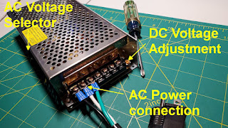
There are two other items of note here. First, before connecting to power, check that the small toggle on the side is set to the proper AC voltage for your country or region. Most of these power supplies will work with either 110V or 220V. Assure this switch (sometimes you need a small screwdriver to reach the toggle) is set properly before connecting to AC power.
Once this is done, connect the AC power and grab your voltmeter or mutlimeter and set it to a range appropriate for a 5V DC range. There is a small adjustment screw (shown in orange in above photo) that allows you to fine tune the output voltage to a precise 5V. This is a necessary step as I've had power supplies that can out of the box outputting nearly 6V and as low as 4V. So you do need to check and set this output power prior to connecting your controller and LED strips.

Connect the leads from your meter to any one of the available (V+) and (V-) terminals. Then use a small screwdriver to slowly turn the set screw until you get 5V out. It is OK if you are slightly higher than 5V, as the components will handle a slightly higher voltage and you are also likely to get a little voltage drop just from the wiring run, but try to assure your final output voltage is between 5.0 and 5.1 V DC.
Once this is done, you are ready to connect your power supply to the controller and LED strip.
Connecting and Routing the Power
First and foremost... even though your controller and LED strips both run off of 5V, the controller (nor breadboard/prototype board) are rated to handle the current load that will be required for more than just a handful of pixels. For example, running anything higher than about 500 mA through your controller pins creates the high likelihood that your controller will blow out and fail. 500 mA is enough current for only about 8 pixels! You also don't want to run more than a couple of amps through a breadboard or prototype board. So in most cases, you'll want to run power to your strips and controller in 'parallel'.

The above is a simple, generic diagram that shows parallel power wiring to the controller and LED strip. While I show use of Wago clips, you can run directly back to the power supply terminals if desired. The idea here is to run your 5V and ground separately to the controller and LED strips. Yes, the ESP dev boards have a 5V pin that outputs 5V. But again, it is meant for only small current. While your LEDs might work for a while (at very low brightness) by running your power thru the board to the LEDs, I can almost guarantee that your controller is going to fail at some point with anything more than a few pixels at decent brightness.
Power Injection
I've mentioned power injection a couple of times, and if you've read anything else on powering LED strips, you've probably come across this term more than once. While your LEDs might receive a full 5V at the beginning of the strip, as the power travels through the strip, resistance from the wiring and components causes the voltage to drop slightly. After enough distance and wire/components are traveled, this voltage drop becomes significant enough that it starts to impact the pixels, as they aren't receiving enough juice to full power all three diodes. This is usually seen as a dropping in brightness and/or a fading of the colors towards pink, red or orange (since the red diode needs the least voltage, it is the last to be impacted). For 5V strips, you may see this start to become noticeable somewhere around 150-250 pixels... give or take a bit, depending upon numerous factors, such as color, effect, brightness, etc.. Eventually, pixels further down the line will simply not receive enough power to light up at all.
This is where power injection comes into play. If you recall from the discussion above about data signal direction, the DC power can flow either direction. This means that we can connect an additional 5V power line anywhere along the LED strip and effective inject or "boost" the voltage back up to 5V. The most common and easiest place to inject power is at the end of the strip. Since the voltage "flows" both directions, these means that you can run somewhere around 300 - 400 pixels just with the original connection at the start of the strip and one at the end of the strip. But you can also inject anywhere mid-strip as well if additional power is needed for even more pixels.
To create power injection, you just need to run wiring for +5V and ground from the power supply or source to the injection point. If the end or injection point is at one of the locations where a default JST connector is installed, recall from above that there were two extra wires available... red and white. These are your power injection wires. Just connect your +5V to the red wire and ground to the white wire and viola... power injection!
But if you need to inject somewhere mid-strip or where these extra wires are not available, just solder your two injection leads to any available +5V and GND copper pad along the LED strip.
 |
| Example of power injection mid-strip |
The clue here is that if your LEDs are dimming or the colors are fading along the strip, it most likely means you need to inject power along your strip.
Other Power and Safety Considerations
Fuse Protection
If you have bought a power supply from a reputable source, it should already come with fault (short), overload and over temp protection. But double-check. If you want to add an additional layer of security (especially in large installs with high amps), you can consider adding a fuse to your installation. While there are a multitude of ways to do this, the easiest is to simply add an inline fuse to your primary +5V power line as the power leaves the power supply.

The size of fuse needed depends on a lot of factors.. gauge of wire used, length of wire runs, size of the project, etc. There are many online calculators that can help you to determine the appropriate fuse size for your particular project.
Capacitor
Some people opt to install a 1000 µF capacity on the voltage line as well. This can help protect both the controller and LED strips from power surges on startup (or other fluctuations). I have installed these on some projects, but don't on most... and have never had a problem on the ones without it. So, it's your call on this one.Bench Testing
While bench testing your install is always a good idea to assure you don't have problems before you make all your final connections and install your project. If you aren't familiar with that term, it basically means setting everything up on your "bench" or table top and running it through the paces to assure everything is working as expected. But I also use the "bench test" as a safety check. For LED lighting projects, I will set the lights to maximum current draw (e.g. full bright white), and let them sit for a couple of hours, occasionally checking the temperature of the various wiring runs, pixels, controller, etc. If any of the wiring or components are starting to get any hotter than just 'slightly warm', then it means that I am not using large enough gauge wire and need to consider using larger wire. The pixels and controller chip might get a little warm, but they should not get too hot to touch. If anything is getting "hot" instead of just slightly warm, you will want to consider making changes before installing in a permanent and/or closed location. This is just my personal final "safety check" before I install anything.
Logic Level Shifter
When talking about voltage and power, up until this point the discussion has revolved around the 5V needed to power the controller and lights. But we haven't discussed voltage related to the data signal between the controller and LED strip. Like the voltage to power the strip, the strip also expects a 5V data signal. However, ESP8266/32 boards only output 3.3V on their pins. To 'boost' the signal from 3.3V to 5V, you can pass the signal through something called a logic level shifter.

Now, many people will claim that you don't really need this extra component. Once the signal reaches the first pixel, the signal is automatically boosted to 5V when passed on to the next pixel. So, the only concern is getting the data signal to that first pixel with adequate voltage. If your wire run between the controller and start of the LED strip is very short, the 3.3V is probably enough to transfer the signal. But it is right on the edge. If the voltage drops even a little more, all kind of problems will occur... flickering, incorrect patterns, wrong colors, etc. And it will be more susceptible to interference.
The cost of a logic level shifter is about $1. If I am spending the money on 100's of LEDs, power supply, aluminum channel (and my time), I'm going to spend the extra dollar to assure that I have a good (and in spec) data signal... whether I truly need it or not. So, you can make your own decision... I include, and will continue to recommend, that you include a logic level shifter when building your own controller (side note... most reputable sites, including the author of WLED also recommend use of a logic level shifter... and they are included on the pre-built board by Quindor I referenced above).
In lieu of a shifter, you can use what is known as the 'sacrificial pixel' method. Remember that the pixel itself will boost the signal to 5V. So, you can cut off a single pixel from your strip and solder that to the controller data line (along with 5V and ground) right on or near your controller and it will work just like the logic level shifter. But to me, it makes a 'messier' install with more potential for failure. However, WLED does account for this option and allows you to 'skip' the first pixel and not light it up if you are using it for a voltage shifter. Again, the choice is yours.
Mounting LED strips
This section is more 'food for though' or recommendations, as there is no specific 'right way' to install LED strips... as this will be highly dependent upon your particular situation.
Most LED strips have a peel off adhesive backing, meaning you can just peel off the backing and just stick them up. While this will work in some situations, the adhesive on these strips isn't the strongest. And the pixels will generate a little bit of heat. If you install these strips directly under something like a cabinet or desk, I can almost guarantee that at some point part of that strip will come loose and dangle. Believe me, I know from experience that this gets frustrating.
In nearly every LED install I do, I reinforce the adhesive using 3M double-sided tape:

This tape is approx. 10 mm wide, exactly like the LED strip. I've yet to have an LED strip come loose when using this tape.
If I have a straight run where I'm installing an LED strip, like for a shelf, under-cabinet, desk, etc. I also like to use aluminum channel made for LED strips. These also have the bonus of including a diffuser to 'soften' the direct light from the LEDs.

The aluminum channel comes in different shapes as well, flat, 45° angled, etc. Small clips are included that let you mount the aluminum strip to just about any flat surface. Note that even when using the aluminum channel, I sill use the 3M tape.
But there are a lot of other ways to mount your LED strips, depending upon your need and particular installation.
Conclusion
There are many, many other things to talk about regarding LED strips and LED lighting. Some of these, like adding a button control, remote control or a microphone for sound-reactive lighting, I cover in other blog articles and YouTube videos. I'll link to some of those, plus other helpful resources below. But building your own LED controller and light strips will give you much more flexibility in terms of features, while also likely saving you money (in some cases, significant dollars).
Links and other helpful info
Links to some of the parts shown
*Some of the above links may be Amazon affiliate links. While these links do not impact your cost, this blog may earn a small commission from your purchase, which will be used to support future projects.
For other DIY controller parts, see my video and blog articles on building your own LED controller.
Other informational links
Build your own LED controller for $6 (YouTube)
Official WLED Site (firmware/software for controller)
Quindor's QuinLED site (lot's of good LED info)
YouTube Playlist (an assortment of my LED projects, with info on various topics)
Supporting this blog and related YouTube channel
If you'd like to support future content on this blog and the related YouTube channel, or just say thanks for something that helped you out, you can use any of my Amazon links to make a purchase at absolutely no cost to you. Or if you prefer to say thanks directly, you can buy me a one-off cup of coffee at:
Many things in this post seem simple and obvious, but for one reason or another they are sometimes forgotten. It was a pleasure for me to read this compendium of knowledge in one place. Thank you.
ReplyDeleteThanks! I cover a lot of LED projects, and sometimes I gloss over the basics... assuming that my YouTube viewers or blog readers already know those things. I forget that sometimes it might be someone first starting out that is doing their very first LED project... and might not know or have the experience with some of those basics. I hope that this blog and related video help to fill that gap for those that might just be starting out... like all of us were at one point in time.
DeleteThanks for taking time to comment!