

This article will cover an outdoor, IP65-rated LED installation using BTF neon rope tube sleeve and WS2812b LED strips. Like my other videos and articles, this will be a DIY project.
If you've read some of my other blog articles or watched my YouTube channel, you've probably noticed that I've done my fair share of LED projects! But in this article, I will be walking through my first outdoor LED installation. In addition, this will also be my largest single installation in terms of both the number of LEDs and the size of the power supply used.
You can see a video version of this installation in my related YouTube video.
Project Plans
Before I get into the step-by-step process, let me cover the initial goals and plans.

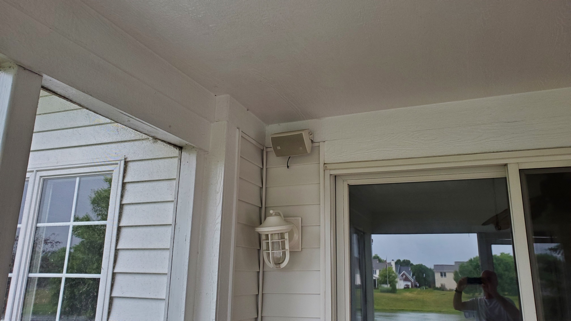
The LEDs will be installed along the top edge of our screened porch, just below the ceiling.
Each of the four sides are approximately 12', with this small bump out in one corner.

This current fixture will be removed and replaced with a waterproof enclosure that will contain both the 5V 60A power supply and the WLED microcontroller. A push button on the bottom of the enclosure will allow toggling of colors and effects without needing to use a phone, tablet or computer.
However, this current light fixture is controlled by a wall switch just inside the sliding door.

To allow this switch to still switch the lights off and on, but to not kill the power to the LEDs so that they can also be controlled by automation, I will be installing a smart relay behind the switch. To see more why this is necessary (and why you don't want to just tape off the switch), see my article on Smart Plug vs. Smart Switch vs. Smart Relay or the related YouTube video on the same subject.
Neon Rope Tube
Thanks to BTF Lighting, who supplied both the neon rope tube and the WS2812b LED strips for this project. The neon rope tube used is IP67 rated (e.g. waterproof) for outdoor installations and also provides better light diffusion over the standard aluminum LED channel I use for most of my indoor projects. To see a comparison, the different varieties of rope tube available, and also how to cut the neon rope tube and install the LEDs, you can watch this YouTube video on comparing BTF Lighting Neon Rope Tube vs. Aluminum Channel. I'll talk more about this cutting the tube and installing LEDs below.
Parts List
Here are all the primary parts that I used for the project. Some items may be optional or are available in different sizes/lengths and may vary for your own particular project. I'll try to note these below.
|
Item/Description |
Notes |
|
Currently not
available via US Amazon |
|
|
|
|
|
Current size
dependent upon LED count |
|
|
|
|
|
Mounting power supply
to back plane |
|
|
|
|
|
|
|
|
|
|
|
|
|
|
|
|
|
|
|
|
|
|
|
WLED Controller Parts |
|
|
|
|
|
|
|
|
|
|
|
Mounting in 3D
printed enclosure |
|
|
Optional |
|
|
|
|
|
Other Miscellaneous
Components |
|
|
Various wiring – 12 to
24 gauge |
|
|
Hot glue or silicone
sealant |
To seal any openings
from water |
|
|
|
Some of these links may be Amazon affiliate links. Use of these links will not affect your pricing, but this blog may earn a small commission if you make a purchase. Use of these Amazon links is one the best ways to show your support for the blog... at absolutely no cost to you!
Of course, you will also need normal tools such as wire strippers, soldering iron and solder, etc.
3D Printed Parts

While not necessary to complete the project, I did design and print some additional 3D printed parts. These include additional end caps, mounting brackets with the tab to hold/conceal the power injection wires and miscellaneous enclosures for wire connections.
Controller
While I generally recommend using a lower cost ESP8266 board (normally a Wemos D1 Mini) for most LED projects, due to the large number of LEDs in this project - approximately 820 - an ESP32 is recommended. Why? Well, according to the official WLED web site:
ESP8288
For good performance, it is recommended that a maximum of 512 LEDs be used per pin.
At 1,000 LEDs, the frames per second is only around 17 fps.
ESP32
Very good performance can be expected at up to 800 LEDs per pin (and up to 1,000 LEDs for good performance.
At 1,000 LEDs, the frames per second is around 70 fps.
So, with just north of 800 LEDs, an ESP8266 would likely suffer from frame rate, meaning that some effects may tend to flicker or not act as expected due to the fact that the ESP8266 just can't handle the processing needed for the number of LEDs. So I opted to use an ESP32 Mini.
As far as the build of the controller, the wiring is basically identical to the D1 Mini version, but due to the slightly larger footprint of the ESP32, a full size ElectroCookie board is needed.
 |
| Click picture to see larger view |
A time lapse video of the build of this controller is available in the YouTube video or you can see a step-by-step guide of the Wemos D1 Mini version in my video Build your own LED controller.
I'd recommend that you flash WLED on the ESP32 Mini before soldering onto the board. See the links at the end of this article for the WLED site.
Cutting the Neon Rope Tube
Before cutting the tube, be aware of the pull string that runs through the entire length of the tube.

When you cut the tube, you will want some length of pull string available on both ends of the cut piece.

The tube is actually easy to cut with a box knife or other sharp blade. But cut partially through the tube and then bend apart and look for the pull string. Use a small screw driver to pull up a little string, then cut with scissors so that you have some extra string on each side of the cut.

To be sure I don't pull too much string and lose the string on the opposite end, I simply tape off the end with a little masking tape.

Installing LEDs in Neon Rope
Once you have cut your tubing to the desired lengths, the next step is to prepare the LED strips. You will want your LED strip to be just slightly shorter than the length of the tube. This will allow the soldered connections for the wiring to be just recessed inside the tubing. This will provide better weather protection and allow the end cap to be installed on the tubing.
Next, the adhesive tape needs to be completely removed from the back side of the strip. If you've used LED strips before, you are probably aware that there is an adhesive backing. When the adhesive tape is used, the LED strip can be attached to most smooth flat surfaces.

But for the LED strip to fit easily into the neon rope tubing this adhesive tape needs to be completely removed.

Starting at the corner of one end, gently peel up the adhesive from the strip. Go slowly and use care. You want to try to remove the adhesive as cleanly as possible and also do not want to damage the wiring within the LED strip.
Once the tape is removed, there should not be any tackiness or sticky tape residue remaining. If there is, you can use a rubber eraser to gently work off the remaining residue.

Through a process of trial-and-error, I found that by using a hair dryer on a medium setting to slightly warm the adhesive helped in the removal process. I just mounted a hair dryer in a position that I could pass the LED strip in front of it as I peeled off the adhesive. In addition, try to pull the tape up at a 90° angle to the strip. Your mileage may vary!

If desired, you can go ahead and solder your wiring leads on to ONE END of the LED strip. If this strip is going to connect to another strip, do not install the second leads yet. It will be difficult if not impossible to pull the lead wires through the tubing. Take note of the LED strip data direction as well.

Using the pull string, tie a slip knot over the first pixel of the LED strip. Give a gentle yank on the string to assure that the knot isn't going to slip off the pixel.

Feed the start of the LED strip into the tubing. Note that the rope tube actually has a slotted section meant to hold the LED strip in the proper position. Now gently begin pulling the string on the opposite end of the tube. The LEDs should feed easily. Try to keep the tube as flat as possible during this step. If you have a longer length of tube and LED strip, it might be helpful to have someone assist in this step... gently feeding the LED strip from one end as you pull from the other. If anything 'snags', stop and back up the strip a little and try again. If the LED strip appear to "jam", then pull the strip back out. Assure the leading edge hasn't bent... and again, try to keep the tube and LED strip both flat as possible while feeding.
When you reach the end of the strip on the feeding end, you may need to work the end of the tube a bit to get your solder joints past the beginning of the tube.

You can then pull the LED strip beyond the end of the tube (assuming you have already attached lead wires to the other end!). You can then remove the string and solder any necessary wires on to this end of the LED strip if you are connecting to another strip, or need to provide power injection.

Once wires are soldered to the other end, you can use the original lead wires to pull the LED strip back so that both ends of the LED strip are contained within the tube.

Install an end cap on both ends of the tube. If the tube will be exposed to direct water or spray, you should add a little silicone sealant (or hot glue in a pinch) to the edge of the end cap and to seal the hole where the wires exit.

I'd also recommend labeling the tubing, especially the data signal direction, as you won't be able to see the LED strips after they are installed in the tube... and since the data signal only flows in one direction, the LEDs will not work if hooked up in reverse.

If feasible, I'd also recommend a quick bench test as you build each segment by connecting your controller and power supply to the date in end of the strip. Better to find out if the strip is damaged or not wired correctly now instead of after they are mounted! This also serves as a bench test for the controller as well. Just remember to update WLED to at least the number of LEDs in your longest strip, as the default is to only light up the first 30 pixels.
Installing the Enclosure
As mentioned above, I will be removing an existing light fixture and mounting a waterproof enclosure box. After removing the fixture, I found that just removing a little of the vinyl plate would allow me to use the electrical box to securely mount my enclosure.

After measuring and marking, holes were drilled in the enclosure and mounted using these holes.

Now, this mounting was only temporary, as I would need to take it back down to drill additional holes for the AC line from behind the enclosure, a hole in the top for the outgoing power and data lines and a small hole in the bottom for the push button that will give some local control over the LED lights. When ready to permanently mount the enclosure, I'll add a little silicone sealant to the back between the enclosure and the vinyl mounting plate to assure no water leaks in through the back.
One nice feature of this enclosure is that it has a removable, raised platform for mounting components like the power supply that will still allow our AC wiring to feed from the back.
But before mounting the power supply, we need to check and calibrate it to assure it is outputting the expected 5V.

To do this, the power supply is connected to a 110V AC source (or 220V if that is the voltage in your location... be sure to set the toggle switch on the power supply appropriately). Then the 5V and GND output is connected to a multimeter. A small screw on the power supply allows you to adjust the output voltage. Due to voltage drop due to wire resistance, it is better to have this just slightly higher than 5V than lower. But don't set it much over about 5.1V.
Once calibrated, it can be attached to the mounting plate.

This particular power supply had mounting holes for M4 screws. So appropriate holes were drilled in the mounting plate and 4 M4 screws and washers securely attached the power supply to the plate.

Note that this is intentionally off-centered. This will allow room for the controller when the plate is installed in the enclosure.

This is how it will all fit in the enclosure. The AC lines will feed from the back (not connected in this photo). The primary 5V output will be fused and will run out a hole in the top of the enclosure along with the signal wire from the controller to the LED strips above. The controller is in the white box on the right, with the blue and black wires at the bottom for connection to the push button.

Here is the completed version, connected to mains power and mounted on the wall of the porch. The mounting was pretty straightforward.

And here you can see the white split conduit running up to a junction box at the top. This junction box will contain connections for the beginning of the strip, along with distribution of the power injection wires. The first segment, or tube, has already been mounted in the above photo, and that's what I'll cover next.
Installing the Shelly 1PM

Without the smart relay, if the wall switch is flipped off, it kills the power to both the power supply and our controller. This means that the devices will be offline and cannot respond to any automations or events (e.g. motion, sunset, etc.). But by adding the smart relay behind the switch, the switch will function just like it did... flip it on to turn on the lights and flip it off to turn off the lights. But now, with the smart relay, we can add automation (Home Assistant, Google Assistant, Amazon Alexa, IFTTT, etc.) to turn on the lights and set things like colors and effects, regardless of the current state of the physical switch. It give the best of both worlds and help with the WAF (or FAF - Family Acceptance Factor).
See my article on Home Automation and the Family Acceptance Factor for more info on why this is important in your smart home.
While Shelly devices come with options for both local and cloud control right out of the box, I'm choosing to flash custom firmware, called Tasmota, to the relay for better options and integration into Home Assistant You can find information on flashing Tasmota to the Shelly 1PM in my blog article on Moving a Switch Outlet or in my related YouTube Video (jump to about the 4:54 mark for the Tasmota flashing process), so I'm not going to repeat that information here.
But I will cover a couple different wiring options, depending on some different pros and cons.
Option #1 - Always on power supply and controller.

In this scenario, the existing physical switch is actually removed from the circuit and the original hot wire from the switch is connected directly to the load. The Shelly is also connected to the AC and to the switch. When the switch is flipped, the Shelly will tell the WLED controller to toggle the current state... e.g. turn the lights off if they are on or vice versa. So, the switch will still turn the LED lights off or on.
The PROS of this method:
- The WLED controller is always on and available.
- Automations or event responses can speak directly to the WLED controller, resulting in faster response.
- The power supply and the controller are always "ON" and cannot be shut off without throwing the breaker or disconnecting the wiring.
- Even though the WLED controller turns the lights "off", the LED strip, controller and power supply will always be drawing power, even with the lights in the off state.

The PROs of this method:
- When the switch (or Shelly) turns off the circuit, everything down line (power supply, controller, LED strips) are powered off and will not draw any power.
- Adds the ability to completely kill the outside circuit in the event of extremely strong weather or any other adverse conditions.
- Automations will be a bit more complicated, as turning on the lights will first require telling the Shelly to turn on the circuit, then interacting with the WLED controller to turn on the LEDs and set any desired colors or effects (again, a power on default can be defined in WLED that will fire whenever the controller boots).
- Automations may be a bit slower due to the time it takes the WLED controller to boot and become responsive. The WLED controller boots relatively quickly, but it can take a second or two. This will result in a delay between flipping the wall switch and the lights powering on. If you have time sensitive automations, you may need to consider the first option or build a delay into your automations to allow the WLED controller to boot before setting any colors or effects.

If I find that the power-on delay is an issue, it is easy to switch to option #1 by just moving one wire on the Shelly relay. You may want to see my results of testing these two different options under the Home Assistant section before you make your own final determination.
Mounting the LEDs and Rope Tube
This step ended up being much more challenging... and took much longer... than I expected. First off, I was fortunate to have printed my own version of extra mounting clips.

The mounting clips that came with the neon rope tube are on the left. These were extremely tight and it was difficult to insert the rope tube. My 3D-printed version is on the right. They are easier to first mount with a small screw and then insert the rope tube easily. The little tab at the top was designed to accommodate the power injection wires that would run from the primary junction box to each corner. That was the plan anyway.
Next, I severely underestimated the number of mounting clips that would be needed. There were only 6 clips included with each 5 meters of neon rope tube. That meant a total of 18 clips. And with my small bump-out, that meant only 4 clips for each 12' side... or one clip about every three feet. I did know that I was going to need to supplement the total number, which is why I printed about a dozen or so of my own clips. But after hanging a couple of sides of the tubing, there was definite sagging between clips. I found that a mounting clip needed to be placed about every 16" to eliminate any droop. And since the clips have to be mounted before the strip is installed, this meant taking the strips down, respacing and adding mounting clips and rehanging the strips a second time. And I had to print another 18 mounting clips to have enough for the entire install... opting not to use any of the clips provided with the rope tubing.
And hanging the strips is really a two person job... at least for my 12' lengths. It took my wife on one end and me on the other, both working towards the center to get the tube mounted and spaced evenly on each side.
But once I was happy with the mounting, it was time to run the power injection wiring to each corner.
Running Power Injection Wiring
The idea was that each power injection wire pair would run from a primary junction box above the power supply/controller enclosure through the tabs on the mounting clips and be inserted into the strip at each corner junction.
 |
| Primary junction above power supply enclosure |
Since the mounting clips were mounted at the ceiling and the tabs pointed toward the wall, it required that the power injection wire be threaded from one end, through each tab, to the other end. Ideally, this would keep the power injection wires out of sight.

After running the power injection wire on two sides in this manner, I wasn't happy with the overall appearance. The power injection lines were clearly visible. And before you ask, while there is room within the tubing itself to run a set of injection wire, they would be right in front of the LEDs and very visible.
So I "unthreaded" all of the power injection wiring I had previously installed. Since my clips were slightly oversized, I found it was possible to push the injection wiring into the clip and behind the actual tubing. This had the added benefit of make the tubing within each clip a little tighter, helping to reduce any sagging between clips.

This was a much better result and the power injection wires are completely hidden. This would not have been possible with the clips that were provided with the tubing. But this brings me to my next design flaw.
Connecting the corners
I had designed and printed smaller junction boxes that I was going to use at each corner. This would contain the connection between the two LED segments and also allow for the power injection.

But as you can see above, I severely underestimate the size of the enclosure needed to hold the various wiring and Wago connectors. It might have been possible to use these boxes if I had soldered and heat shrink wrapped the connection, but soldering in this tight corner would have its own challenges. So, I decided to redesign and reprint the corner junction boxes.

Once the corner junctions were redesigned and reprinted, all the wiring and Wago clips fit neatly inside. A short piece of white heat shrink tubing was added between the end cap and the junction box to provide additional water protection and to also hide the wired.
All told, it took nearly three entire days to complete the install. This was partially due to the difficulty in working with the neon rope tube, as it would tend to twist and fall out of the clips (I eventually added some zip ties about every third bracket to prevent this). And as usual, there were other unexpected issues that arose... like most projects.

This bumped out corner took a while to resolve, and in all honesty, it could have been done neater.... but this was nearing the end of day three and I was ready to put this project to bed! However, the end result turned out pretty good, and except in a few cases if you are looking for it, no wiring is visible anywhere in the install.

Other finishing touches
There were just a few other final items to address, mostly adding a small amount of clear silicone caulk to any openings where water might seep in, like on the top of the primary enclosure where the flex conduit entered. Time will tell how well things hope up through the various Indiana seasons!
Final Results
Here are a few additional photos, taken just after dusk. As always, it is tough to take photos of LED lights as they tend to overwhelm the camera.

First is a photo of the lights just on standard white. There is PLENTY of light available, and this was taken at only 50% brightness. Even at that brightness, it is ample light for reading, playing cards or any other activities. In fact, I found that near 100% brightness was actually too bright for sitting in outdoor darken conditions.


And of course, there are all the various colors. Again, this is probably brighter than I would normally use, but they can be dimmed down to just barely glowing to provide more of an ambience at night.


And here are a few more photos taken from the backyard.... again at about 50% brightness. Naturally, WLED also has hundreds of effects as well, but those are tough to show in a photo. Take a peek at the YouTube video to see a few of these.
Home Assistant, Automations and Lag Time
WLED has a native integration into Home Assistant and will likely be automatically discovered. These means that not only can the lights be controlled via Home Assistant, but they can be used for automations. Just a couple of ideas would be to have the lights come one when motion is detected (with maybe something like a strobe effect!)... have the lights slowing come on at sunset and fade off at sunrise, etc.
However, if you recall up above where I discussed the two different options for installing the Shelly relay, one option had the WLED controller (and power supply) powered up at all times. The other option, and the one I selected, shuts off the power to the controller and power supply. These means that the board must power on and boot up before any additional commands can be sent.
There is currently about a 1.4 - 1.6 second delay between the time the wall switch is flipped on and the lights actually turn on. So, this is about the amount of time that will need to be added to any automations or scripts that first turn on the Shelly relay (and powers the lights) before any additional commands to set effects or colors can be issued.
So, I decided to create a simply Home Assistant script that turns on the lights and sets an effect. I will be comparing the reaction time between sending these commands directly to the WLED controller that is already powered on (simulating the Shelly wiring option #1) vs. the time and delay needed to first turn on the Shelly and then sending the same command to set an effect.
Test 1 / Shelly Wiring Option #1
In this script, the commands are sent directly to the WLED controller, as it is always powered on:
sequence:
- service: light.turn_on
data:
entity_id: light.back_porch_leds
brightness: 128
effect: "Candy Cane"
This is a pretty simple script. We can set a brightness level and an effect in the same service call that turns on the lights.
When executed, the lights came on already set to the defined brightness level and with the specified effect running.
Time between launching the script, lights turning on and setting an effect: <0.2 seconds.
Test 2 / Shelly Wiring Option #2
For the second test, we must add a command (aka service call) to first turn on the Shelly 1PM relay to power up the power supply and the WLED controller. Then the same command to turn on the LEDs, set a brightness and effect is sent to the WLED controller:
sequence:
- service: switch.turn_on
entity_id: switch.back_porch
- service: light.turn_on
data:
entity_id: light.back_porch_leds
brightness: 128
effect: "Candy Cane"
When launched as written, the lights did turn on after about 1.7 seconds, but this is just because WLED has a default preset defined at boot. The the second command to actually set the brightness and effect executed before the WLED controller booted, so it wasn't received. This means that I will need to add an intentional delay between the two commands.
While I initially mistakenly thought that since the lights powered on in less than 2 seconds, adding a two second delay to the above script would allow it to function. But what I hadn't accounted for was that it takes significantly longer for the WLED controller to connect to the Wi-Fi and be reachable for the second command to set the brightness and effect. In fact, while the delay varies based on Wi-Fi conditions, my testing showed it took an average delay of 6-8 seconds after the board powered on (and the lights came on) before a second command could be sent. This delay is obviously not going to work for certain time-sensitive automations, like motion detection (unless I'm happy to use a boot preset via WLED).
So, for this test and wiring scenario, the time between launching the script, lights turning on and setting an effect: ~10 seconds.
Again, I can eliminate this delay by rewiring the Shelly 1PM using option #1, but this would also mean that the LEDs, WLED controller and power supply would be drawing a small amount of continuous power, even when the LEDs were set to "off".
I will probably deal with the issue through Home Assistant automations. For example, if I want motion detection only at night, I can turn on the Shelly 1 during night hours when I want fast automation response, then turn it back off during the day to conserve the energy. Or I could re-do the wiring and add a relay or 'kill switch' to the enclosure box.
There is one other point worth mentioning when using wiring option 2. When the power is shut off to the controller, Home Assistant will throw occasional errors in your log file complaining about an API timeout. This doesn't cause an issue, but if you are a "log watcher" like I am, then these errors might bother you... or you can just clear the log and forget about them!
Final conclusions
This was easily my largest single LED installation... and my first outdoor install. But more than anything else, it was by far the most labor intensive and time-consuming LED project I've done. Unfortunately, a large amount of this extra effort was due to use of the neon rope tubing. Not only did it take significantly more time to prepare the LEDs, but trying to mount the tubing, eliminate sagging, hiding the power injection lines, along with 3D-printing additional end caps and mounting clips, added significant effort and time to the project.
While the neon rope tube provides IP67 waterproofing and also provides nice diffusion, if I were to do this project again, I would like use IP65 or IP67 rated WS2812b strips and aluminum channel for the mounting. The aluminum channel would be much, much easier to mount, LED preparation would be much easier and there would be no sagging, resulting in neater, straighter lines. And, if run correctly, the power injection lines could be hidden within the aluminum channel as well.
The BTF Lighting neon rope tube is a high quality product and there could definitely be situations where a straight rigid aluminum channel simply wouldn't work. But in my case, for this porch install, the flexibility of the rope tubing simple wasn't needed and in fact it ended up being a slight detriment.
Let me know down in the comments if you have any thoughts or questions!
Links:
Videos
Blog Articles
Other
Supporting this blog and related YouTube channel
If you'd like to support future content on this blog and the related YouTube channel, or just say thanks for something that helped you out, you can use any of my Amazon links to make a purchase at absolutely no cost to you. Or if you prefer to say thanks directly, you can buy me a one-off cup of coffee at:
No comments:
Post a Comment
To help eliminate spam and to keep all conversations civil, submitted comments are moderated. Therefore your post may not show up immediately. Please be patient as most reviews are completed within a few hours.