As you can see from the specs on the supply itself, it can output up to 17A @ 3.3V, 22A @ 5V and 18A @ 12V. There are some other limitations when using more than one output, but I will fuse for those, which I will cover later, and in most of my cases I will only be using a few amps max per channel. However, you may need to adjust your build based on the specs of the computer power supply you will be using.
Removing the Power Supply
 CAUTION! Always assure the power has been removed from the power supply before touching any components. In addition, if the power supply has recently been powered on, allow a few minutes before messing with any connections. Due to large capacitors within the power supply, it retains a charge for a number of minutes, even after power has been disconnected. If you are not comfortable working with electricity and electrical components, consider asking someone with more experience for assistance
The first step is to free the old power supply from the computer. This process will vary from computer to computer, but the steps are similar.
First, trace and locate the wiring from the power supply to the connectors located on the motherboard and peripherals. Carefully detach each connector, noting that some connectors, like the primary motherboard connection, may have retaining clips that need to be squeezed or opened to remove the connector. In addition, wiring may be routed under other components, like in my picture above where a bundle of wire ran under the processor cooling shroud (indicated by a dotted line).
Now, you could make the removal process a bit easier by just cutting off all the connectors and pulling the wire back. But since I didn't know at the time if I might use the connectors in my new power supply (I didn't), I wanted to keep all the connectors intact if possible. Just removing a couple of screws allowed the cooling shroud to hinge out of the way and gave me access to pull the wires back with the connectors still attached.
Once all the connectors are free, the power supply is normally mounted in the chassis with just a few small screws. Remove all the screws and gently lift the power supply out of the chassis.
If it doesn't easy come loose, check for some sort of retaining clip. In my case, there was a small clip at the bottom of the case that needed to be depressed before the power supply would slide out.
Identifying the Wiring
Once the power supply has been removed, the next step is to identify the various wire colors and their purpose. Most ATX-style power supplies use standard colors, but there may be variations in some manufacturers. Dell, for instance, was well-known for using proprietary or non-standard parts. And since I was taking this power supply from an old Dell server, I need to find/verify the wiring. The easiest/first place I started was with the Dell primary motherboard connector, which listed the pins on the motherboard connector and their purpose.
I labeled the primary motherboard connector, based on the pin indications on the motherboard itself, and from that and the documentation, identified the following wire colors and purpose (another reason why I was glad that I didn't cut off any connectors yet):
|
Pin Number
|
Signal Name
|
18-AWG Wire
|
|
|
1
|
+3.3 VDC
|
ORANGE
|
|
|
2
|
+3.3 VDC
|
ORANGE
|
|
|
3
|
GND
|
BLACK
|
|
|
4
|
VCC (+5V)
|
RED
|
|
|
5
|
GND
|
BLACK
|
|
|
6
|
VCC (+5V)
|
RED
|
|
|
7
|
GND
|
BLACK
|
|
|
8
|
PS_PWRGOOD
|
GREY
|
|
|
9
|
P5AUX
|
PURPLE
|
|
|
10
|
V_12P0_DIG (+12V)
|
WHITE
|
|
|
11
|
V_12P0_DIG (+12V)
|
WHITE
|
|
|
12
|
+3.3 VDC
|
ORANGE
|
|
|
|
|
|
|
|
13
|
+3.3 VDC
|
ORANGE
|
BROWN
|
|
14
|
-12 V
|
BLUE
|
|
|
15
|
GND
|
BLACK
|
|
|
16
|
PWR_PS_ON
|
GREEN
|
|
|
17
|
GND
|
BLACK
|
|
|
18
|
GND
|
BLACK
|
|
|
19
|
GND
|
BLACK
|
|
|
20
|
NC
|
NC
|
|
|
21
|
VCC (+5V)
|
RED
|
|
|
22
|
VCC (+5V)
|
RED
|
|
|
23
|
VCC (+5V)
|
RED
|
|
|
24
|
GND
|
BLACK
|
|
Note that pin 13 has two wires connected, with no indication as to the purpose of the brown wire. In addition, other wiring bundles also contained a yellow wire, not identified above. So, a little more searching led me to the wiring colors for the actual power supply itself. This also included max voltages for the various buses. I used that information, along with the above to create the following working chart:
|
ID
|
Max Amp
|
Color
|
Count
|
Notes
|
My Use
|
|
+3.3V
|
17
A
|
ORANGE
|
7
|
|
|
|
+5V
|
22
A
|
RED
|
10
|
|
|
|
+5V (fp)
|
2
A
|
PURPLE
|
1
|
Stndby Pwr
|
Stndby LED / Meters
|
|
+12V (A)
|
18
A
|
YELLOW
|
5
|
|
|
|
+12V (B)
|
18
A
|
WHITE
|
4
|
|
|
|
-12V
|
1
A
|
BLUE
|
1
|
|
Will not use
|
|
|
|
|
|
|
|
|
3V3 Sense
|
|
BROWN
|
1
|
|
|
|
GND
|
|
BLACK
|
20
|
|
|
|
Power On
|
|
GREEN
|
1
|
Power On
|
Toggle switch
|
|
Power Good
|
|
GREY
|
1
|
Power OK
|
Power On LED
|
Total Max Power: 305W
+3.3V & +5V Max Power: 150W
+12V & -12V Max Power: 288W
So, I now have each of the wire colors identified. I also created a count of each color type. I wanted this because all the wiring from the power supply is only 18 gauge wire. To handle the larger amps, I will need to bundle some of the wires together to safely handle the load.
The standby wire (purple) can only handle two amps, but since it is live even when the rest of the power supply is "off", I can use this to power the standby LED and the two digital voltmeters.
This means that as soon as the power supply is plugged in (and a load is detected... more on this in a bit), both the digital meters and standby LED will light up. This lets me know that the meter is plugged in (live), but the primary main power is still turned off.
The brown wire (from above, shared a pin with an orange/3.3V wire) is the 3.3V sense wire. The power supply uses this to measure voltage drop due to resistance and will adjust the actual voltage to keep it at a constant 3.3V. So this will need to be connected to the primary 3.3V bus in the desktop supply.
The green wire is the power on wire. Normally, this is connected to the main power switch of the PC (like a button on the front that you use to turn on the PC) I'm going to repurpose this for a toggle switch that allows me to turn the main power off and on (although the standby power will remain on even when the main power is off).
Finally, the grey wire reports that the power supply is OK. I'll connect that to my main power "ON" led, so if anything isn't working properly, this light will remain off. It also lets me know when the main power is on and the connections are energized.
Finding a case and panel layout
OK... with everything identified on the power supply, I needed to find a suitable enclosure and design the approximate layout of the front panel and controls. After some searching, I located a good candidate on Amazon:
 |
| You can find a link to this enclosure in the parts list above |
This was a perfect size, and the two front sections would make a nice separation between the controls, with fixed voltage outputs on the left and the variable voltage output on the right. It came with two removable metal face plates that I initially figured I could cut and drill to size (note the use of "initially"... more in a bit). It also had ventilation slots which would be important for the PC power supply since the cooling fan output is opposite the power cord connection, meaning heat would be vented into the box.
With the dimensions, I created an initial panel layout:
This wouldn't be the final design, as I would eventually eliminate the second toggle, add the LED lights, consolidate the multiple ground connections for the fixed voltages into a single ground, and more. Unfortunately, I didn't photograph the final "paper design", but it can be seen in the final build.
For the back panel, I just needed a square opening to allow access to connect the power cord and to supply ventilation to the power supply.
I would eventually move the power supplies spec sheet to the back and add a clip for storing the power cord, but I learned one thing from cutting the back panel. The enclosure specs do not say what these panels are made of, just that they are metal. But they are heavier than something like aluminum duct material. In fact, with my limited and mostly wood-working tools, I struggled just to try to get a neat large square... using a combination of drill, jigsaw and Dremel. And if you look closely at the photo, it's still a pretty messy and jagged cut. Maybe fine for the back, but I knew that it was going to be near impossible to get the precise layout and look for all the controls on the front panel. So, I opted to abandon the metal front panel and print my own with a 3D printer.
But because the front panel was longer than my printer bed would allow, I had to break the print into two parts... the left panel and right panel.
But it was perfect because the enclosure had a plastic off-center support post that would neatly divide these two sections.
The four corners already had mounting holes and screws for the metal plate. I just had to add mounting holes to the center plastic post to hold my two separate panels.
The end result turned out nicely, even though the blue filament I used is slightly darker than the rest of the enclosure. But it is still much more precise and neat than if I had tried to cut the original metal panel with the tools I had. If you want to see more details or download copies of the 3D .stl files that I used, you can find them on Thingiverse and I'll leave a link at the end of this article.
But now it was time to move on to mounting the power supply and wiring it all up.
Preparing and Mounting the Computer Power Supply
So, since I decided I was going to need to bundle wires for higher current, I opted not to use any of the existing connectors and would be cutting them all off.
But as you can see above, the leads coming out to the primary motherboard connector are pretty short. This bundle also contains many of the "specialty" wires, like the sense wire, standby power, etc. that weren't available anywhere else. And if I cut off the connector, leaving just a bit of wire in case I wanted to repurpose this for a later project, it will make the available wire even shorter. So, I opted to cut some of the retaining zip ties and remove the top of the power supply to see if I could free up some length.
Removing eight small screws allowed the top of the unit to be lifted off. And by moving all the wires to one side, I now have plenty of wire to run to my planned busses inside of the enclosure. So, I opted to leave the top cover off.
WARNING! Due to the large capacitors in the power supply, a charge is maintained within the unit even after the power supply is unplugged. Do not touch any components within the unit for at least a few minutes after unplugging from main power!
You can see an example of this in my YouTube video, where I show the power meters and LED light remain on for a full one minute after unplugging the power supply. Removing the top cover is dangerous, so please use extreme care. In my case the unit will be enclosed within my outer box, but if you opt to leave the cover off please assure that the primary power supply is somehow covered or protected from accidental touches. My next step was to find a way to securely mount the power supply in my new enclosure.
In the photo above, I have cut off all the default connectors from the wiring. I drilled a couple of small holes in the bottom of the enclosure and the power supply and used angle brackets to secure the front side of the supply. For the side and the back, I was able to use existing screw holes (and screws) from the original power supply and small holes drilled in the side and top panel of the enclosure. Note that the A/C power connection is aligned with back side of the enclosure. This means that the cooling fan will be pointed towards the front... and into the enclosure. This is why it was important for the enclosure to have the venting in the side panels. Having the top cover off the supply will also help with heat dissipation. The bonus is that all the wiring is pointed in a good direction for mounting and connection to terminal blocks and other components.
Terminal Wiring
I decided to run all the connections from the computer power supply to a terminal block for distribution to the rest of the components. This allowed me to cut away a bunch of extra wiring and keep things a bit more tidy and organized.
I mounted two 8-way terminal blocks to the bottom of the enclosure using small nuts and bolts. The bottom terminal in the photo are all ground wires. The top terminal block contains all the other wiring we will need. For all the supply voltages to be used, multiple wires (at least 3) are bundled together. Recall that this is needed to handle the higher amps using only the 18 gauge wire from the supply.
So, starting from the second terminal on the right and moving left are:
- Bundle of white wires (+12V bus 1)
- Bundle of yellow wires (+12V bus 2)
- Bundle of red wires (+5V)
- Bundle of orange wires (+3.3V) + brown sense wire
- Single purple wire (standby power)
- Single grey wire (power OK)
- Single green wire (power on)
Note that for the orange bundle, the brown 3V3 sense wire is added. Recall from the above, that the power supply will use this sense wire to regulate its power output. Depending upon the power supply, it may not power up without this sense wire, or it may result in inaccurate output voltages. So if your power supply has a sense wire, be sure to connect it to the proper voltage "bundle".
For the last three, only single wire is needed (and only one is available), as none will be carrying any significant current.
There is only one other wiring connection that needs to be made from the power supply itself. That is an aluminum enclosed resistor that is required to introduce a load to the power supply.
Providing a Load
As a safety precaution, most computer power supplies will not power on unless a load is detected. In a normal computer, that load is provided by the motherboard, fans, disk drives and other peripherals. However, in our bench top power supply, there may not be a load connected. And even if there is, it may be too small (like a microcontroller that might draw less than 500mA) for the power supply to turn on. This can be overcome by wiring a resistor to the +5V bus and ground. In my case, a 10W, 10 Ohm resistor provided enough resistive load for the supply to power on.
One side is wired to a red +5V wire coming from the power supply and the other side to a ground wire. Note: this resistor will get VERY HOT! This is normal, but take care not to touch the resistor with your bare hands. It is also important to mount or find a location in your enclosure to assure the resistor does not come into contact with other components or wiring. It can definitely melt other wires.
I opted to mount mine to the ventilation output side of the power supply itself. The metal sides of the power supply acts as a heat sink and the cooling fan of the power supply also moves air across the resistor.
Power Switch and LED Indicators
While the wiring for all the components really isn't that complicated, it can be hard to describe from a photo alone. So, for each of the components, I'll show a photo and a simplified drawing, followed by a description to try to make everything as clear as possible. Clicking on any picture or diagram should pop it open in larger window, which might make it easier to see.
Note that all these connections will be low current, so 20-22 gauge wire should be fine. I'll start with the toggle switch. I wired mine so that the light for the switch turns on when the switch is turned on, but you can wire it so that the light is on any time the system is powered. First, connect to the green wire of the power supply (via the terminal block) to the outside silver terminal. The green wire is the 'power on' to the power supply. Connect a ground wire to the center terminal. I used female spade connectors for the connection to the toggle switch.
Next is the standby LED (green led in my case, but you can substitute any color.. just adjust the value of the resistor accordingly. This is connected to the purple (+5V standby power) wire of the power supply. This means that as soon as the power supply is plugged into the wall, this LED should illuminate. Add an appropriate resistor between the LED and a ground connection.
The "power on" LED (red) connects to the grey (power OK) wire of the power supply and add a resistor between the negative (shorter) leg and the ground connection.
All ground connections can be tied together and connected to any available ground terminal on the ground terminal block. Oh, and I simply hot glued both the toggle and LEDs in place from the back side.
Fixed Voltages
This next section covers the fixed voltages side of the device. Namely, 3.3V, 5V and 12V. It is designed and wired so that two of these three voltages can be used simultaneously if desired. Before getting into the pictures and diagram, let me cover just a bit about the LED meter so it makes a little more sense.
The LED meter can be wired in a couple of different ways... direct power, where the meter is powered by the same source it is measuring, or via independent power where the meter gets it power from a separate source than it is measuring. The separate power source can be anything from 4-30 VDC.
 |
| Manufacturer's wiring diagram |
Since we have a standby 5V power source available, we can power the meter from this source. Wiring this way will allow the meter to power on when the power supply is in standby mode. It will show zeros until the power is flipped on via the toggle switch. You'll see this wiring in the picture and diagram that follows.
This diagram is pretty self-explanatory, but I'll add some notes and comments. First off, for all the wiring between the power supply terminal block that will be supplying our outgoing power (represented by the thicker lines in the diagram), I used 16 gauge wire. Now, most of my electronic projects use lower current, generally never more than a few amps. If you expect to use higher current for longer periods of time, you should consider 14 gauge or even 12 gauge for these wire connections.
The thin wires in the diagram are from the power meter and were part of the supplied wiring harness. I think these are 24 gauge (or maybe even 26 gauge), but they will be carrying very little current. The thin yellow wire is connected to the positive terminal bridge on each side of the meter.
Also note that the thin red wire from the meter is for the independent power source and connects back to the purple standby wire on the terminal block. If you recall from above, we also connected the green standby LED to this same terminal. Eventually, there will be a third wire connected to this terminal to power the meter on the variable side. In situations where I need to make multiple connections to a single terminal or post, I generally stripped and joined those wires together and crimped into an appropriate size fork or ring connector. The connection was secured with heat shrink tubing. You can see example of this in the above photo, but here's a close up of those three connections to the single terminal for the standby power:
This is generally easier than trying to connect multiple fork connectors to a single terminal screw in the terminal block.
Otherwise, for the 3.3V (orange), 5V (red) and 12V (yellow), a connection is made from the power supply terminal block to the outer connection of the fuse holder. The inner connection of the fuse holder is then connected to the female banana plug/terminal for the front of the panel. Note that there is no soldering required for this step! All connections are either via crimped ring or fork connectors. The fuse holders and banana plugs are mounted in the panel with nuts and the meter snaps into place via mounting tabs on each side.
This completes the fixed side of the benchtop power supply. If you only need these fixed voltages, then you're done! But if you also want the advantage of a variable output, read on as that is what I'll cover next. For more information on using the benchtop power supply, including how to use multiple outputs simultaneously, see the section that follows the variable wiring under Testing and Use.
Variable Voltage Buck Converter
Now, we are going to move to the other side of the front panel, where we will setup variable voltage and amperage outputs.
To create a variable voltage, we are going to use a variable step-down buck converter:
As you can see, the step-down buck converter takes an incoming fixed voltage (12V in our case) and can step that down to an voltage between 1V - ~11V. It can also adjust the current to a fixed value (e.g. 2.5A). This is accomplished by turning the tiny set screw on the two potentiometers... one for voltage and one for current. But since this buck converter will be inside our enclosure, we need a way to change the voltage (and current) without taking the cover off the case and getting a tiny screwdriver! This particular buck converter can also handle up to 20A, which is more then enough for the 15A max that we will fuse for.
To make the voltage and current adjustments possible from the front panel, we are going to remove the built-in potentiometers and replace them with our own that can be accessed from the front panel.
This is really the only part of the entire project that requires some soldering skills. The first step is to de-solder the existing blue potentiometers from the buck converter. This should be connected via three pins, just like the new potentiometer we are going to replace it with. Carefully solder 3 new lead wires to the old pads on the buck converter.
One of the existing small blue potentiometers should be labeled CV (constant voltage)... this will be your voltage adjustment... and the other should be labeled CC (constant current), the amp or current adjustment.
Connect the three leads to the new potentiometer. I would suggest that you make a temporary connection to the new potentiometer and go ahead and connect the buck converter IN to a temporary 12V supply and the OUT to a multimeter set to the appropriate DC voltage range.
The reason for this testing is that different values of potentiometers will give you different range/sensitivity adjustments. For me, I found that a 100K potentiometer gave me a decent balance of sensitivity vs. range (how much you turn the knob vs. how much the voltage changes).
Now, you repeat the same process for the second potentiometer. But here's where you need to exercise some care. You need to assure none of the wiring or solder joints make contact between the CV and CC wiring. I used a heavy coat of liquid electrical tape to assure isolation between the connections.
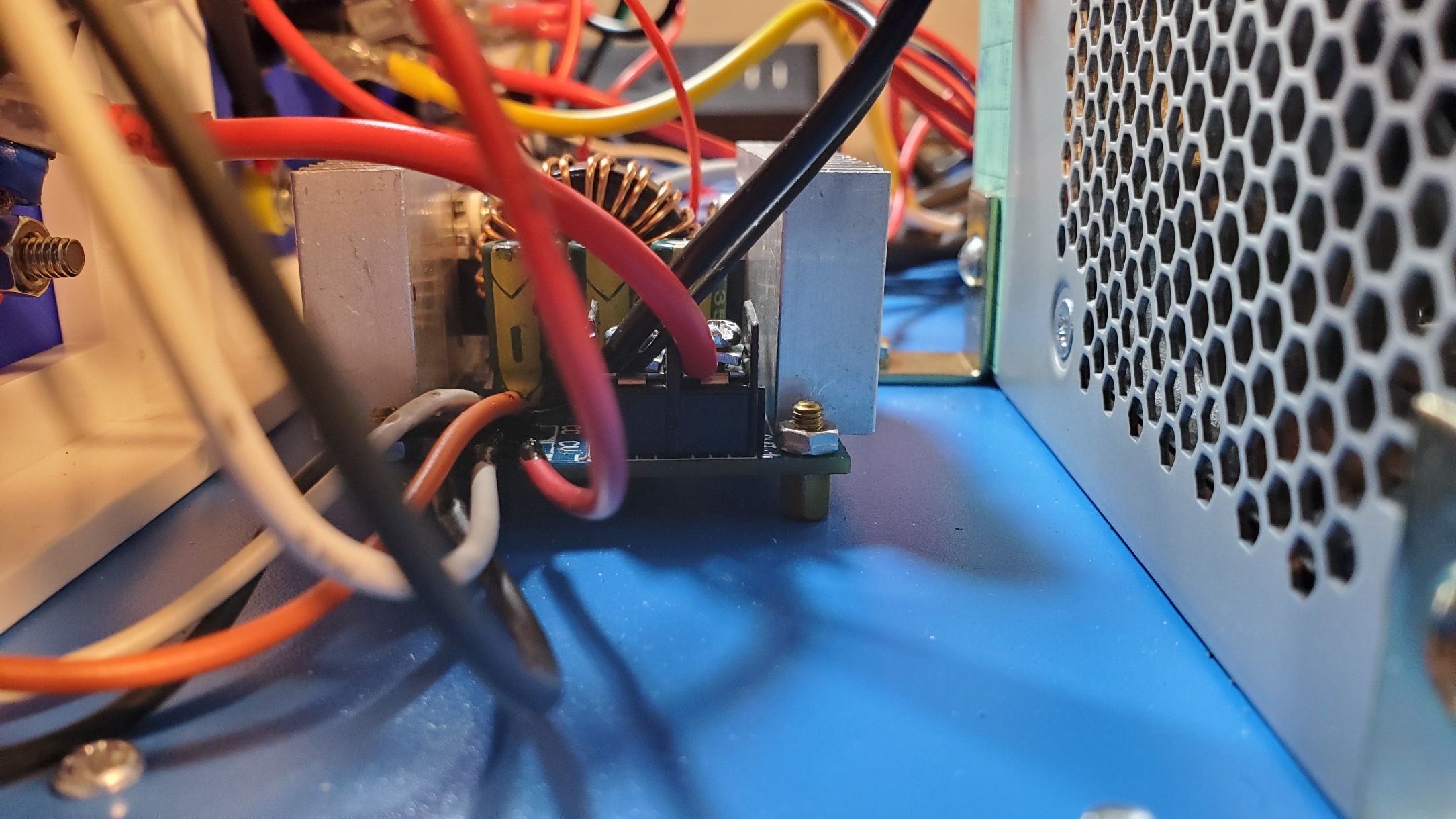
Before moving on to the panel wiring, let's take a look at the final connections and mounting of the buck converter in the enclosure:
For the incoming voltage side of the buck converter, we want to use the second +12V bus from the power supply. If you used the yellow wires for the fixed side, then use the white wires for the buck converter... or vice versa. Since each bus has an independent 18A max rating, by using both busses, we can use both the variable and fixed outputs simultaneously, each with its own max amp rating.
The two potentiometers are wired as described above and the OUT side of the buck converter will connect to the panel in much the same design as a single voltage on the fixed side, which I'll cover next. The entire buck converter is mounted to the bottom of the enclosure, using small metal PCB standoffs:
Speaking of mounting things to the bottom of the enclosure, I think it is a good time to show the bottom of the case with all the components mounted inside:
It's pretty easy to drill small holes through the metal bottom for mounting components And since the enclosure includes nice feet, it keeps any screw heads from contacting the surface.
Now, moving on to the the final step... the variable panel connections
Variable Voltage Panel Connections
As usual, I'll start with a photo and basic diagram:
The wiring of the potentiometers is covered above, so I won't go over that again, as is the incoming voltage to the buck converter using the second +12V bus line and ground from the power supply terminal blocks. The rest of the wiring is very similar to a single fixed voltage described above.
The positive (+) output from the buck converter connects to the fuse holder (grey circle with black center). The other terminal of the fuse holder connects to the positive terminal/female banana plug (red). The small gauge yellow wire from the meter also connects to this same terminal.
Both the large gauge and small gauge black wires from the meter connect to the negative (-) terminal of the buck converter. The large gauge red wire from the meter connects to the negative terminal/female banana plug (black).
Finally, the small gauge red wire from the meter connects back to the power supply terminal block's standby voltage line (purple). This allows the meter to power on when the system is in standby mode.
That's it! That is all the wiring needed for both fixed and variable outputs, with up to three simultaneous outputs. Replace the enclosure cover.
Adding Fuses
Before powering everything up, we need to add the appropriate size fuses to our fuse holders. As mentioned above, I will primarily use this power supply for low current projects. So, I fused each output to be below the maximum available from the power supply:
|
Output/Voltage
|
Max Rating per Specs
|
Fuse Used
|
|
3.3V fixed
|
17
A
|
15
A
|
|
5V fixed
|
22
A
|
20
A
|
|
12V fixed (bus A)
|
18
A
|
15
A
|
|
|
|
|
|
Variable
(12V bus B)
|
18
A
|
15
A
|
Fuses also protect from any unintended shorts. Note that while each output is fused under the max, it will still be possible to exceed the maximum power supply limit when using multiple outputs. I'll cover that scenario under the Testing and Use section next.
At this point, the benchtop power supply should be ready for use. I did also add labeling to all the inputs, outputs and fuses as you can see in many of the photos. But before actually hooking up sensitive electronics to the power supply, we need to do some testing and possibly some calibration.
Testing and Use
Let's start with some testing, and calibration of the meters if necessary. Once everything is secured and the top of the enclosure replaced, assure the front panel toggle switch is in the "OFF" position and plug the unit into A/C power using the original computer power cord (or an appropriate replacement if you no longer have the original).
If wired as described above and all is working well, the standby LED and the meters should power up. The meters should all read zeros.
Testing meter and fixed voltages
We'll start by testing the meter and output voltages on the fixed side of the supply. To use the meter, a short ring or banana plug jumper is ran from the desired voltage terminal (3.3V, 5V or 12V) and the 'IN' terminal to the left of the meter. Then we connect our load or device to be powered to the "OUT" terminals on the right of the meter. For testing, I'll connect a multimeter set to the appropriate DC range.
Once the connections are made, flip the toggle switch to power on the supply. If the internal power reports OK, the red 'on' LED should light up and both the LED meter and your multimeter should report a voltage of 3.3V. A small discrepancy of 0.1-0.2V is probably OK... at least it is acceptable to me. Since the computer power supply is regulated, the output should be both accurate and consistent.
I then repeat the test for both 5V and 12V by simply placing the unit back in standby via the toggle switch and moving the jumper to the other terminals, and turning the unit back on.
Note that in all cases, the digital LED reports precisely the expected voltage. If you find that the meter is off, there are calibration screws located on the back side of the meter.
You can adjust both the meter's voltage (V_ADJ) and current (I_ADJ) with these calibration screws. To test the amp reading, you would need to apply a known load to the output terminals, but the process is basically the same as the voltage. Just remember, if you do need to access components inside the enclosure, disconnect the main AC power cord and allow the unit to sit for a few minutes to dissipate power collected in the capacitors before removing the cover! You can also toggle the front power switch from standby to ON after unplugging the unit to the wall to help facilitate the dissipation, as this will draw any remaining power out of the capacitors. You may see the LED meters or LED indicators flash or power on briefly as this power is drawn.
Note that you can also test the voltage output directly, bypassing the LED meter, by connecting to the desired output terminal and the lower ground terminal.
In fact, it is this method that we will use to access multiple outputs simultaneously. But more in that after we test the variable output.
Testing the variable output and meter
The testing process here is similar to the fixed voltage test, except the input voltage is selected by rotating the knob for the voltage adjustment. The multimeter is connected to the output and I'll compare the output between the two meters at various points along the range, assuring I test at least a low reading, a couple of mid-point voltages, and something towards the top end of the range.
If you have some common voltages you tend to use on a regular basis, it would be good to check those particular voltages, for example, I often use 7.4V Li-ion batteries in my projects, and in other cases a standard 9V battery, so I verify those voltages in my testing.
(Side note: For some reason, in all my testing, the multimeter reported 0.1V higher than the meter. When I tested with a second multimeter, the results matched the LED meter to the first decimal in every case. For some reason, the multimeter shown always tends to report 100 mV high. But for all but the most sensitive projects, a 100-200 mV variance should not be a problem).
Like the fixed side, you can test current by connecting a known load. However, unlike the fixed side, the second knob here allows you to limit the current to a given value. The meter supports a current of up to 20A, so there is no problem running up to the fused max of 15A. The manufacturer of the buck converter recommends heat sinking when running over 10A, but I also placed the buck converter in front of the power supply ventilation fan, so it should be fine running up to 15A for all but extremely long time frames.
Again, if the meter appears to be reporting wrong values as compared to the multimeter, you can adjust both the voltage and current readings of the LED meter with the backside adjustment screws as shown above under 'Testing meter and fixed voltage'.
With everything tested and calibrated, your new benchtop power supply is ready for use on your next project!
Using Multiple Outputs Simultaneously
While the above testing process pretty much showed how to use a fixed or variable output, with the way the unit is wired, it is possible to output up to three different voltages simultaneously to drive different projects or parts of a project at the same time. You can use any combination of two fixed voltages and one variable voltage at the same time.
As you can see in the above example, the power supply is simultaneously supplying three different voltages: - 3.3V via a direct connection to the 3.3V jack and the lower GND
- 5.0V via the jumper to the meter and the meter outputs
- 9.0V via the variable output
You can use any combination of two fixed voltages by using one direct connection and one jumped connection to the LED meter. A third output, of any voltage within range, can be used via the variable output. This is extremely handy for projects where you may need multiple voltages (using a common ground, as all grounds are connected within the power supply). One example might be a string of 12V LED pixels that use a 5V controller. There are numerous other possibilities.
PLEASE NOTE IF USING HIGHER CURRENTS FOR YOUR PROJECT
Even though each individual output is fused below the max output current for that particular connection, it IS possible to exceed the ratings of the computer's power supply when using multiple outputs simultaneously with high current, even though each individual output is at or under its own maximum.
Remember the stated maximum from the power supply from way back at the start of this article:
- +5V and +3V shall not exceed 150W
- +12VA and +12VB shall not exceed 208W
- Total output shall not exceed 305W
So, for example, if you are using the 3.3V at the full maximum of fused 15A (52.5W) and the 5V at the full max of 20A (100W) simultaneously, you would technically be using 152.5W, which exceeds the maximum power supply limit of 150W
Or, say you are using the fixed 12V and the variable output also set to 12V, both pulling the max 15A. This would be a total of 360W, which exceeds both the +12VA and +12VB max and the overall max for the power supply.
But if most of your projects are using just a few amps each, you can safely run three simultaneous output. But if you are going to use multiple outputs with higher currents, just verify you are remaining under the stated maximums.
Conclusions
This is a pretty easy project if you have just a little experience with electronics and an old PC laying around that you can repurpose into a usable device instead of recycling (or worse, have it end up in a landfill).
You will probably spend somewhere in the neighborhood of $50-$100 in parts, depending on what you already have on hand. And most of that cost is made up by the enclosure, LED meters and the buck converter. If you truly don't need the variable output, you could eliminate the second meter, buck converter and purchase a smaller enclosure to cut costs. As is, you'd still have two simultaneous fixed outputs, and you could easily modify it to be three outputs by adding another ground connection to the front panel. You could then output 3.3V, 5V and 12V all at the same time.
For me, this was both a fun and educational project. And the best result is that I ended up with a new piece of equipment for future project build!
Links
Supporting this blog and related YouTube channel
If you'd like to support future content on this blog and the related
YouTube channel, or just say thanks for something that helped you out, you can use any of my Amazon links to make a purchase at absolutely no cost to you. Or if you prefer to say thanks directly, you can buy me a one-off cup of coffee at:


.jpg)


No comments:
Post a Comment
To help eliminate spam and to keep all conversations civil, submitted comments are moderated. Therefore your post may not show up immediately. Please be patient as most reviews are completed within a few hours.