

I'll only be covering the basics here, and providing some diagrams, parts lists, etc. For the step-by-step process of building your own set of letters, I recommend watching the video linked above.
Parts List
*The following are Amazon affiliate links. While this does not impact your pricing, the blog may earn a small commission to support future projects if you make a purchase.
|
QTY |
Description / Link* |
|
1 |
|
|
1 |
|
|
1 |
Logic Level Shifter (optional, but
recommended) |
|
3* |
5 pk Magnetic Pogo Pin Connectors (*1 pair per letter, plus
at least 1 for controller) |
|
1 |
|
|
1 |
5M WS2812b RGB Led Light Strips (more or less
depending upon number of letters) |
|
1 |
5V 15A Power Supply (adjust appropriately
for number of LEDs) |
|
|
Optional Items |
|
1 |
|
|
1 |
Normally-open pushbutton (for local button
control) |
|
1 |
IR Receiver (for IR remote control) |
|
1 |
|
|
1 |
|
|
1 |
|
|
1 |
Pk ¼” Braided wire sleeve (if power injection
or multi-row lettering used) |
|
1 |
Hefty Deluxe Strong
and Deep Dinner Plates 10.25” – find at local grocery |
The dinner plates are used as the diffusers. There are many alternate materials that you could use, but the dinner plates are cheap (around $2 for 15 plates here) and easy to cut. It is important to carefully check the bottom of the plates before purchase, as some appear to have a stamped recycle symbol on the bottom of the plate and others do not. Here's a picture of the packaging if it is helpful:

3D Printed Letters

For the letters (each around 5" x 4"), I used Hatchbox Black PLA filament. My printer is an Ender 3 Pro. You must use supports for all letters and enclosures.
If you do not have a 3D printer, there are multiple online services that will print and ship your designs for you. You can design your own, or use my designs, and an online printing service to create whatever sign(s) you'd like. Unfortunately, I do not have the capacity to print and ship letters myself.
Controller
The controller is the standard WLED controller I have used in multiple other projects shown both in this blog and on my YouTube channel. In fact, I have both a blog article and YouTube video that gives step-by-step instructions on building the controller, so I'm not going to repeat that here. Instead, I'll just provide a couple of reference diagrams:
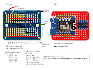
Note that the push button and IR receiver are completely optional and only needed if you wish to control the letters via a local button and/or IR remote. When all connected, the overall wiring diagram looks like this:

Again, this is shown with both the button and IR receiver. Here's what it all looks like when installed in the controller enclosure:

Installing WLED
Of course by using WLED, you will have all the 100's of different lighting effects available for your sign. You also have both the web and mobile app for control and if you have Home Assistant, WLED integrates natively so you can include your sign in any automations. You can install WLED by following the instructions provided on the official WLED web site. Just remember that, by default, WLED is configured for just 30 pixels. Be sure to increase this number as you add letters (otherwise, you'll be like me and think you have a wiring problem as the second letter only lights up the first 6 pixels).
The WLED site also contains information on configuring the push button and IR remote if you opted to install those.
General Wiring Notes
It is imperative that you maintain consistency on wiring for each letter. It is also a must that you observe the data direction of the LED strips. While DC power can flow either direction, recall that the data signal only travels in one direction within the LED strips.
You can use your own system, but here's how I wired mine:
- +5V (red) was always connected to the top pin of the magnetic connectors
- Data (green) was always connected to the center pin
- Ground (black) was always connected to the bottom pin.
- Data in used the female (or flat) connectors and the data signal always entered on the left side of the letter - when seen from the front.
- Data out used the male (pogo pin side) connectors and data signal always exited the letter on the right - when seen from the front.

While it is easy to identify the left and right sides for some letters like A or B, it is easy to get things flipped around with letters like H or O. For this reason, my designs have a very slight raised area on the inside edge of the DATA OUT side. Keep track of this raised area to assure you are connecting the correct wiring to the correct side. This will also be critical for magnet installation/polarity when assembling the letters.
Assembling the letters
I'm not going to cover the step-by-step process here, as you can see it in the related YouTube video. But here is the general order (and a couple of notes) that I used and found work the best:
- Install the secondary magnets by placing a small amount of hot glue in the provided holes. Be sure to note polarity or your letters will repel each other instead of attaching and sticking together. Also assure the magnets are flush with the surface or they will prevent the pogo pins from connecting.
The small scratches are from removing excess glue after dry, but they won't show. - Cut and install the diffusers. Whatever material you are using (if not the Styrofoam plates), use a very limited amount of hot glue to keep them in place, but not so much that it interferes with the LED strip installation.
- Prepare the LED strip. Cut a length of 24 pixels (at 60 pixels/m) and tin the pads at both ends with a little solder.
- Tin the input end of the magnetic three pin connector (the 'flat'/female side in my design). Solder short wire leads at 90° to the connector and the other end of the wires to the starting end of the LED strip (note the LED strip data direction - assure you aren't soldering to the DATA OUT end).
- On the DATA OUT end, solder three wires approx. 8" long, aiming back towards the strip. These wire leads will wrap around the bottom of the letter and connect to the data out connector.
- Install the LED strips on the inside of the letter. Use care to set the strips into the corners. If done properly, the end of the strip should come within an inch or so of the start, but should not overlap.
- Run the wire leads you soldered previously along the side and bottom of the letter over to the data out connector. I like to use just a dab of hot glue in a couple of spots to hold the wire in place.
- Cut the wire leads to length, strip, tin and solder to the DATA OUT connector.
- Test. Don't forget to assure WLED is set to the proper number of pixels of the number of letters you are connecting!


Power Injection
You should be able to link somewhere around 10-12 letters before voltage drop creates the need for power injection. If you notice that the letters towards the end of your sign are fading or shifting colors (towards red or orange), it's a sign you need to add power. However, this is pretty easy to do. Just create an 'injection lead' by wiring a DATA IN connector (flat/female) to the +5V and GND pins, with enough wire to run back to the power supply:


You can then run this wire behind, under or over your sign to make it less visible. You should be able to get a chain of at least 20 consecutive letters with power at the start and end of your sign.
Multi-row Signs
If you wish, you can create multi-row messages:

Cutouts for secondary magnets are also provided on the top and bottom of the letter design so that the letters can be stacked in columns or offset by a half letter (as shown above). Note that the secondary magnets are not required for the second row to work, but are just provided to help the rows 'stick' together if desired.
For the wiring, it is similar to the power injection above. However, this time you will include the data wire to the center pin on the output end of the top row, and instead of running back to the power supply, you will wire an male end on the opposite end of your wiring run. Basically, you are making a "patch cable" that connects the output side of the "N" in the above photo to the input side of the "C". You might be tempted to just connect the "N" to the "M" in the second row, but remember that the data signal only runs in one direction. If you wish to make this shorter connection, then the data signal would need to be reversed and run in the opposite direction for all the letters on the bottom row. But you could do it that way... the letters just won't be interchangeable between the rows due to different data flow directions.
Summary and Other Ideas
There are other ways to construct LED signs similar to this. In my case, I wanted something that I could change quickly and easily without removing any wiring. By magnetically connecting the letters, I can hot-swap the letters at any time without even powering down the controller. Let me know down in the comments if you have other ideas!
Links
YouTube video of the step-by-step process described above (and in more detail)
Supporting this blog and related YouTube channel
If you'd like to support future content on this blog and the related YouTube channel, or just say thanks for something that helped you out, you can use any of my Amazon links to make a purchase at absolutely no cost to you. Or if you prefer to say thanks directly, you can buy me a one-off cup of coffee at:
No comments:
Post a Comment
To help eliminate spam and to keep all conversations civil, submitted comments are moderated. Therefore your post may not show up immediately. Please be patient as most reviews are completed within a few hours.