

There are many how-to articles and videos on creating LED stair lighting. But many of these require substantial modification of the existing staircase or adjoining walls. I wanted to create a similar effect using WLED, ESPHome and Home Assistant that didn't require modifying my existing stairs.
I loved some of the videos that I saw on interactive, or motion-controlled stair lighting. But nearly all of these required major renovation. While giving a more 'professional' installation, if you have viewed any of my other articles or videos, you know that one of my primary goals is that all smart home features be easily removable and/or restored or original state as we will likely sell our home at some point in the next few years. So my approach is to provide a similar functionality without any permanent changes to the stairs.
UPDATE: After feedback from a YouTube viewer (thanks DorffMeister!), I have replaced my PIR motion sensors with time-of-flight (TOF) distance sensors. This solved a nagging problem with the bottom motion detector and the open staircase. Due to the opening at the bottom of the stairs, motion would often be triggered (and the lights turned on) just by walking by the bottom of the stairs. While the PIR motion sensors work fine in most cases, the TOF sensors offer an alternative. You can see the upgrade in this YouTube video and read more about it below under the motion detector section.
Part List
As usual, I'll provide a parts list of what I used for this project.
|
QTY |
Description |
Notes |
|
2 |
This will vary based
on size of stairs |
|
|
1 |
Three will be needed
for this project |
|
|
1 |
|
|
|
1 |
|
|
|
1 |
Only 1 is needed for
this project |
|
|
2 |
|
|
|
1 |
|
|
|
1 |
|
|
|
1 |
Only 1 is needed for
this project |
|
|
|
|
|
|
TOF Alternate Sensors |
See update under motion sensor |
|
2 |
section below |
And some additional or optional parts
|
QTY |
Description |
Notes |
|
|
|
|
|
|
Various colors and
lengths |
|
|
|
Wire – 18 to 24 gauge |
|
|
|
3D Printed Enclosures |
|
|
|
Solder, Soldering iron,
etc. |
|
Note: Some of the above links may be affiliate links. This does not affect your pricing, but the blog may earn a small commission towards future projects.
My Requirements
While yours will likely be different, here were my requirements for this project:
- No major modifications or non-reversible changes to existing stairs
- Power source and control box on one side only
- Minimal exposed wiring / neat appearance
General Overview
Here is a general overview of how the system will be configured:
 |
| Not to scale - click to enlarge |
There are different options here. For example, you can eliminate the 5V wall charger if desired and wire the one end of the USB cables directly to the 5V power supply. In my case, I already had an outlet with USB ports available, so I ran the USB cables directly to the AC/charger. I'm also showing Wago lever nuts for splitting the leads. You can use standard wire nuts, solder the wires together, etc. In addition, your most convenient AC outlet may be on the opposite side... or even at the top of the stairs. Regardless, the same general wiring concepts will apply.
This is very similar to other LED projects, but with a couple of key differences. First, we have two independent LED strips (one for each side of the stairs), so we run power directly from the power supply to each strip. More importantly, we are taking the single LED data line (green in diagram), splitting it and running the signal to each LED strip. In effect, this means that the same signal is going to both strips... and both strips will respond exactly the same and stay in sync... if both sides have the same number of LEDs. More on this below.
LED Strip Installation
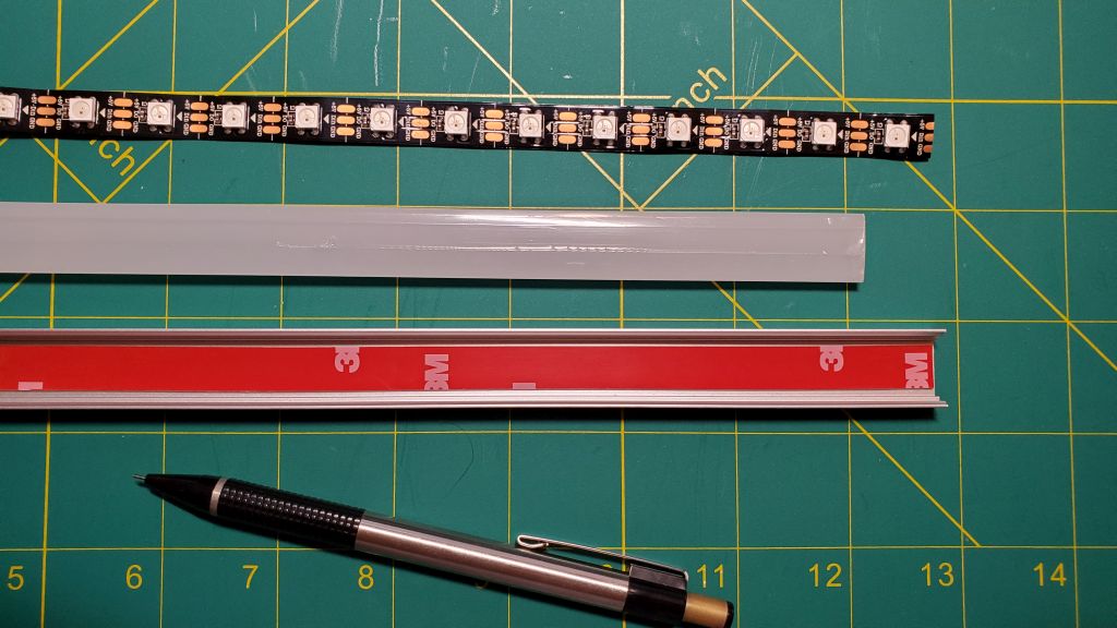
WS2812b LED strips generally come with an adhesive backing. However, I've found that this adhesive is not very strong and will tend to fail over time, especially with the small amount of heat generated by the LEDs when fully lit. Add to the fact that I did not want to "stick" anything to the stair stringers that might be difficult to remove or mar the finish when removed, so I opted to use aluminum channel specially designed for LED strip lighting.

And due to the nature that the adhesive on the LED strips isn't that strong, I always opt to add a little 3M double-sided tape to the channel, then attach the strips to this tape (after removing the LED strip backing):
Install identical channels and LED strips (same number of pixels) on each side of the staircase. Before installing the LED strips in the channel, solder leads (either JST connectors or adequate wiring lengths to reach the eventual controller and power supply locations) to the end of each side of the LED strips:

Carefully note the data directional arrows on the LED strips. If you are installing the controller at the bottom of the stair case, the arrows on each side of the stairs should point 'up' the staircase. Alternatively, if installing the WLED controller at the top of the stairs, these arrows should point 'down' the staircase. Both sides should point the same direction. Note that the LED strip on the opposite side of the power supply and controller will require substantially longer leads. I recommend initially leaving plenty of extra wire... it can always be cut to length later.
Install the aluminum channel (with 3M double-sided tape) on the stringers. Then carefully install the LED strips in the channel with the leads soldered on.

Motion Detectors
Note: The first section is the original install using PIR motion sensors. The updated version using TOF sensors, as described at the start of this article and seen in this YouTube video follows.
The wiring of the motion detectors is pretty simple and straightforward:

The VIN pin of the PIR sensor is connected to the 5V of the D1 Mini, GND to G and the OUT pin of the PIR is connected to D6 on the D1 Mini. You can also use the 3V3 pin on the D1 Mini to VIN of the PIR.... check the specifications of your particular sensor. The D1 Mini will be powered via the micro USB port.
On the subject of PIR sensors, many of the lower cost options may experience electrical interference due to a lack of shielding. This will lead to false triggers and cause your stair lights to come on at random times. The PIR sensor I linked in the parts list above has worked well for me without random triggers.
I enclosed the motion sensor assembly in a 3D printed enclosure. I added "fins" to limit motion detection to a specific area.
 |
| Top motion detector |
 |
| Bottom motion detector |

Both motion detectors are then powered via the USB cable to either a 5V wall (phone) charger plugged into AC power, or the ends of the USB cables can be cut off and the USB cable wired directly to the 5V 40A power supply (take care to observe polarity). Only the power lines from the USB cable will be used. If connecting directly to the power supply, simply cut and terminate the unused data wires.
The D1 Minis will be flashed using ESPHome and will be shown in Home Assistant as a simply binary sensor (type: motion). More information and the full ESPHome code is shown below.
Updated Time-of-Flight (TOF) Distance Sensors:
The upgraded sensors use the same base enclosure (just with a different lid) and the same USB cable for power as the above PIR sensors. The only difference is the sensor and the wiring.


As you can see, both sensor types use the same base enclosure. In my case, I just unplugged the USB cable from the PIR sensor, connected it to the TOF sensor and mounted the new box using the same holes from the old enclosure. The link to the .stl files for printing this enclosure (with both lid types) can be found at the end of this article.
WLED Controller
I have an separate blog on creating the WLED controller, installing the WLED software, initial setup and integration into Home Assistant. See Building your own LED light strip controller for details. However, there are two modifications to this build for the stair lights:
1. Instead of one outbound data line that will connect to the LED strips, we will need two... one for each side of the stairs as shown in the overall wiring diagram above. You can simply add a second data out line (green wire in the diagram) to the same output pin of the logic levels shifter (e.g. HV1) or split the data line after it leaves the controller (but don't do both!). By duplicating the data signal to both sides of the stairs, the lights will always remain in sync as they are receiving the same data signal, if both sides have the same number of LEDs (see below if this isn't the case in your install).
2. You need to select a power supply with enough power to fully light up all the LEDs (both sides). But when setting up WLED, only enter the number of LEDs on ONE side of the stairs as the total number of LEDs and cut the power supply setting in half. This is because we are duplicating the setup, as far as WLED is concerned, on the opposite side of the stairs. For instance, if you have 220 LEDs on one side (440 total with both sides) and a 40 amp power supply, enter your info WLED as follows:

Note that I used 18 amps instead of 20 (for my 40 amp power supply). Just to be extra cautious, I like to limit the amps to less than the maximum of the power supply. The LEDs will still be very bright at this setting.
What if one side has more LEDs than the other?

So, what do you do if your stairs are curved or has a landing and you have more LEDs on one side vs. the other? I'll refer to the rather crude, and not-to-scale drawing above to explain. And for this purpose, the LED data line is connected to both LED strips at Pixel #1 at the bottom of the stairs
First, to determine the total number of LEDs for the purposes of selecting a power supply, you need to use the TOTAL number of LEDs... 200 in the above example. The power supply needs to be sized to provide adequate power to all the LEDs.
But, when entering the number of LEDs into the controller firmware (WLED or custom firmware), you should only enter the number of LEDs from the longer (or larger) LED strip. This would be 125 in the above example. Why? Well, the LED controller is sending out a single signal to light up certain LEDs, based on pixel number or position. Since the highest pixel number available (on either side) is pixel 125, if we enter the total of 200, then the controller will try to send a signal to light up pixels 126-200, which don't exist. This won't cause an error, but will cause a "lag" for certain effects, like a wipe or chase effect, because the controller will be taking time attempting to light up pixels that don't exist.
So, what happens on the "shorter" side in this case? Well, it depends on the LED effect chosen. If you are using some sort of sequential effect that light up the LEDs in order (or reverse order) like chase or wipe, then the lights will appear to be in sync part of the time and out-of-sync at other times.
In a sequential effect, the controller is basically sending a signal that says 'Light up pixel 1, then light up pixel 2, then pixel 3, etc.' all the way to the total number of pixels. If we start the effect at the bottom of the stairs (pixel 1), then the lights will stay in perfect sync.. up to pixel 50. At that point, pixels 56-75 will light up in sequence. On the right, or short side of the stairs, this will light up the pixels all the way to the top of the stairs. But on the left (long) side, pixel 75 only reaches the top of the landing. At that point, the remaining 50 pixels will light up on the long side. Signals for pixels 76-125 on the short side will just be ignored, as those pixels just don't exist.
When reversing the direction, the controller is going to light up pixel 125, then 124, 123, etc. This means that the first 50 pixels are going to light up on the long or left side before anything happens on the right side. Once the signal is sent to light up pixel 75, the first LED will light up on the short side. This will continue until pixel 50, where the landing is lighting up on the long side, but the top section of stairs are lighting up on the short side. Once pixel 50 is reached, the lights will once again be in sync... and stay in sync down to pixel 1.
What can be done about this? Well, not much (sorry). That's just how addressable LEDs work. However, use of other effects that do not light up the LEDs in sequence may be much less noticeable in terms of synchronization due to different number of LEDs. You may need to experiment with different effects and find one that works best for you.
Final Assembly
Simply connect everything together as shown in the above diagram.... 5V and GND from the power supply to the WLED controller and each of the LED strips. Two data lines (from the same output) will run from the WLED controller to each LED strip as well. Whether you wish to use JST connectors, spade connections or direct soldered connections is up to you. I like having the ability to disconnect components if necessary.
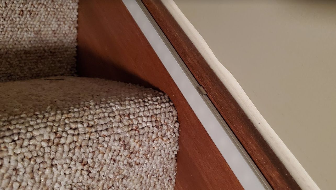
Finally, will be finding the best solution for you for the wiring runs.. and to make them as inconspicuous as possible. In my case, I ran the wiring to the opposite side of the stairs under the lip of the bottom tread and used Velcro cable grip (it is available in various colors) to both hide and keep the wiring in place:

While this isn't necessarily that 'hidden' or attractive when viewed from this angle (photo taking while lying on the floor), in all honesty, it is barely noticeable when standing or going up/down the stairs:

Again, one of the goals here was to not make any permanent modifications to the stairs (or the carpet in this case). The entire installation could be removed in about 15 minutes and the only remaining indication of anything prior would be the very small screw holes in the stringers from the aluminum channel mounting clips.
ESPHome Code
IMPORTANT UPDATE! I have now moved all the code for both ESPHome and the Home Assistant automation and entities into a Github repository. This repository also contains more information and multiple options on how to install and integrate these items into your Home Assistant configuration. Please see the following repository:
===============
The following information has been superseded by the code and information in the Github repository listed in the above update. The following information is simply left here for those that may have used the information in the past, or for those very familiar with editing YAML and Home Assistant configuration files.
===============
Note: The code shown here is for the original PIR sensors. You can find the updated ESPHome code for the TOF sensors in the Github repo listed above or in this gist file.
binary_sensor:
- platform: gpio
pin: D6
name: "Stair Motion Top"
device_class: motion
This is for the top motion sensor in my case. Similarly, you add the same binary sensor information to the node for the bottom motion detector:
binary_sensor:
- platform: gpio
pin: D6
name: "Stair Motion Bottom"
device_class: motion
filters:
- delayed_on: 500ms
Notice that I have added a half second delay for my bottom sensor. This is due to the fact that the opposite side of the stairs are open and motion is detected as someone approaches the stairs (nothing I could really do to block it), so by adding a 1/2 second delay, the lights actually come on as an individual starts up the stairs. You may or may not need this delay... or the time may be different... in your case.
Once you've updated the YAML configuration, compile and download the binary file. Then you can use ESPHome Flasher or other utility to upload the binary file to your D1 Mini.
Note: With the most recent release of ESPHome, it is now possible to complete the initial upload of your ESPHome configuration via USB right from the ESPHome configuration page. But this currently requires SSL/HTTPS for your Home Assistant install. This may change in the future, but for now, you can compile and download the binary file and upload via ESPHome Flasher or other utility.
Home Assistant Entities and Automations
IMPORTANT UPDATE! I have now moved all the code for both ESPHome and the Home Assistant automation and entities into a Github repository. This repository also contains more information and multiple options on how to install and integrate these items into your Home Assistant configuration. Please see the following repository:
===============
The following information has been superseded by the code and information in the Github repository listed in the above update. The following information is simply left here for those that may have used the information in the past, or for those very familiar with editing YAML and Home Assistant configuration files.
===============
Note: If you are not experienced with YAML automations, I have another video that will walk you through, step-by-step, on how to recreate my automations using the Home Assistant UI/Automation Editor: Recreate a YAML Automation Using the Home Assistant UI
binary_sensor.bottom_stair_motion
binary_sensor.top_stair_motion
light.stair_lights #WLED entity for stair LEDs
WLED will also create some additional sensors and switches, but for the purposes of automation, these are the only three entities with which we are concerned. But there is two additional entities we need to create. One is an input_boolean, and you can create it via the UI helper function in Home Assistant, or via YAML... whichever you prefer. Here is the YAML:
stair_auto_leds:
name: Stair Auto LEDs
initial: on
This is created so that we can easily toggle on/off the automations that cause the lights to come on with motion. You may wish to disable the feature at certain times.
The second entity is a timer. This is used to shut off the motion-activated lights if the opposite motion detector doesn't get triggered. This might happen if someone starts down the stairs, stops and reverses direction and the other motion detector never fires.
stair_motion_timer:
No other information is needed. This is simply created under your timers: section in your configuration.yaml, or in your separate timers.yaml if you have one.
Automations:
I'll describe the highlights and certain sections of the automations to control the LED lights below. But you can see the entire automation file (in plain text/copyable format) in my Github Gist Home Assistant WLED Stair Lighting. For this example, someone is coming down the stairs.
Note: Version 2021.12 (and later) of Home Assistant made major changes in how WLED services are called. The updated version is shown below the old version:
Start lights when top motion detected (Home Assistant v2021.11 and earlier):
- alias: Top Motion Lights On
trigger:
platform: state
entity_id: binary_sensor.stair_motion_top
from: 'off'
to: 'on'
condition:
- condition: state
entity_id: input_boolean.stair_auto_leds
state: "on"
- condition: state
entity_id: light.stair_lights
state: 'off'
action:
- service: wled.effect
data:
entity_id: light.stair_lights
effect: 'Wipe'
reverse: true
speed: 220
- service: light.turn_on
data:
entity_id: light.stair_lights
rgb_color: [255,255,255]
- service: timer.start
data:
entity_id: timer.stair_motion_timer
duration: '00:00:15'
Start lights when top motion detected (Home Assistant v2021.12 and later - changes highlighted in bold):
- alias: Top Motion Lights On
trigger:
platform: state
entity_id: binary_sensor.stair_motion_top
from: 'off'
to: 'on'
condition:
- condition: state
entity_id: input_boolean.stair_auto_leds
state: "on"
- condition: state
entity_id: light.stair_lights
state: 'off'
action:
- service: number.set_value
data:
entity_id: number.stairs_speed
value: '220'
- service: switch.turn_on
data:
entity_id: switch.stairs_reverse
- service: light.turn_on
data:
entity_id: light.stair_lights
rgb_color: [255,255,255]
effect: "Wipe"
- service: timer.start
data:
entity_id: timer.stair_motion_timer
duration: '00:00:15'
This automation is triggered by detected motion by the top motion sensor. It checks our input_boolean to assure that the auto-lights are enabled and that the lights are currently off. If both of these are true, it set the WLED effect to 'wipe', reverses the wipe direction (since we want the lights to wipe from the top down) and sets a speed for the effect. It then turns the lights on and starts a 15 second countdown timer.
Stop lights when bottom motion detected:
- alias: Bottom Motion Lights Off
trigger:
platform: state
entity_id: binary_sensor.stair_motion_bottom
from: 'off'
to: 'on'
condition:
- condition: state
entity_id: input_boolean.stair_auto_leds
state: "on"
- condition: state
entity_id: light.stair_lights
state: 'on'
action:
- service: light.turn_off
entity_id: light.stair_lights
In this case, when someone reaches the bottom of the stairs and triggers the bottom motion detector, we check again if the auto-led function is enabled and that the lights are currently 'on'. If so, the lights are simply toggled off.
Turn off lights after timer expiration:
- alias: Stair Timer Expires
trigger:
platform: event
event_type: timer.finished
event_data:
entity_id: timer.stair_motion_timer
condition:
# Assure no motion occurring
- condition: state
entity_id: binary_sensor.stair_motion_top
state: 'off'
- condition: state
entity_id: binary_sensor.stair_motion_bottom
state: 'off'
action:
- service: light.turn_off
entity_id: light.stair_lights
If 15 seconds have elapsed after the lights are triggered (or whatever time you defined in the 'lights on' automation) and no motion has been detected, simply turn off the lights. This might occur if someone starts down the stairs and reverses direction... never crossing the opposite sensor.
Two additional automations are required... that are simply the opposites of the ones above.... lights on with bottom motion, and lights off with top motion. Again, the full code is available at Home Assistant WLED Stair Lighting (HA 2021.11 or earlier) or Home Assistant WLED Stair Lighting Updated (HA 2021.12 or later).
Additional Notes
- You may need to adjust the WLED speed setting and/or the timer length, depending upon your install.
- You are not limited to using the 'wipe' function of WLED. You can use any of the available effects by passing in the effect name in the automation. See the WLED Wiki Effects List for a complete list of effects.
- You can also use any color you prefer and set other options. See the Home Assistant WLED Integration documentation for more details.
Final Thoughts
There are much fancier, more professionally made LED stair lighting systems. But my goal was a simple solution that did not require any modifications to the existing staircase. Your mileage may vary! Note that if you have substantially longer stairs, a mid-staircase landing or other situations different than mine, you may have to make some adaptations in your installation... including power injection at some point in your LED strips (likely required if you see flickering or color fading at the far end of the strip), or even an additional motion detector at a landing or 90º bend.
Also remember that you have the full gamut of WLED at your disposal. You aren't limited to just motion detection events, but can color your stairway with a multitude of colors and effects for holidays, parties, special events... or just because!
By request, if you have a 3D printer here are my basic designs that I used for both the motion detector enclosures and the Electrocookie/WLED controller enclosures:
Supporting this blog and related YouTube channel
If you'd like to support future content on this blog and the related YouTube channel, or just say thanks for something that helped you out, you can use any of my Amazon links to make a purchase at absolutely no cost to you. Or if you prefer to say thanks directly, you can buy me a one-off cup of coffee at:
Hi can you make video how to do this in Home assistant from this part (Home Assistant Entities and Automations)
ReplyDeleteThe home assistant part can be a little confusing ResinChemTech recently helped me . . . I'm more than happy to try an help. Might help me build my yaml and configuration skills.
ReplyDeleteAndrzej and Sprocket,
ReplyDeleteI'm happy to assist as well... especially as it relates to my code. I'm a yaml guy... I've never built a single automation in Home Assistant via the UI. I had to learn yaml before the UI version was available and I'm sticking with it! If you have particular questions or need help with a particular part of the code, just let me know.
Are there any stl files for the printed pir case with the fins?
ReplyDeleteYep... I threw them up on Thingiverse. You can find them here: https://www.thingiverse.com/thing:4969716
DeleteFirst, let me write this: thank you very much for your time, which you spend on creating this blog. I come here a lot and your ideas inspire me, they are very useful. However, I ran into a problem that I can't get over. In your post titled "Simple Motion-Activated LED Stair Lighting" you used the description about Home Assistant and how to connect it. I have all the elements needed to complete the project ready, but when I started handling HA, I realized that your description refers to its older version, and the one I am currently using is newer and slightly different from your description. Especially in a place that concerns: Home Assistant Entities and Automations. Is there any chance that you will go back to this good project and try to describe again more clearly the steps needed to implement it?
ReplyDeleteThanks for the kind words! Yeah... that's one of the issues I have with Home Assistant. Every month they release a new version and sometimes the changes are significant and "break" things. The latest version (2021.12) breaks a lot of things with WLED... and I have nearly two dozen WLED installs that are all going to break and need to be fixed. I have another viewer that had working stair lights and the lastest HA upgrade broke his. I'm going to upgrade in the next day or two to determine what all needs to be fixed and reach back out to him with the necessary updates. Would you be willing to drop me an email describing your issue(s) and I will be more than happy to try to assist you. You can email me at: resinchemtech.diy@gmail.com It's just a little hard to try to troubleshoot and fix issues in the comment section!
ReplyDeleteNote that I've now updated both the blog article and the linked gist files with the necessary changes for the latest release of Home Assistant. The original code applies to HA 2012.11 or earlier, while the updated code applies to HA 2021.12 or later.
ReplyDeleteHow did you do the torpedo effect at 2:45 in the YT video?
ReplyDeleteI replied to this over in YouTube, but I'll repeat here. That effect is called "Fireworks 1D" and it is only one of over 100 different lighting effects provided by the WLED software that is installed on the controller. I didn't have to do anything other than select the effect from the WLED web interface.
ReplyDeleteAwesome. Thank you.
ReplyDeleteThanks for your work with this! Amazing! I'm currently in the process of setting everything up. My question is that you say to install the same amount of LEDs on each side of the staircase. Well I have a landing with a 90 degree turn so one side would need more LEDs then the other. Is there any way to make this work still? I can build the boards and everything just not big on the programming. Thanks in advance.
ReplyDeleteTim
The reason for the same number of lights is that the controller data signal is split and it assures both sides stay in sync. However, that isn't a requirement... you'll just need to set up WLED with the maximum number of pixels on the long side. It won't hurt the short side, WLED will just send the signal to light up the "phantom" pixels that don't exist.
DeleteAs an example, let's say you have 100 pixels on one side and 75 on the other. You'll tell WLED to use 100 pixels. In the effect example I used (wipe), WLED will light up the first pixel (on both sides) and continue to light up pixels one after another until it reaches 100. On the short side, after pixel 75, the signal won't do anything since all the lights are already lit. But it won't crash or anything. Even when running in reverse, WLED will start with pixel 100 down to 1. The first 25 "pixels" on the short side won't exist, but it will start lighting up in sync with the long side at pixel 75.
I hope that makes sense! Basically, you won't need to do any "custom" programming to make it work... just tell WLED the maximum number of pixels on the long side of the stairs. Let me know if you have any other questions! Good luck with your project.
Perfect! Should be easy enough! I will post back when completed (might be a while... Lol)to let you know the results. Thanks again!
DeleteTim
Wouldn't it be possible to take the dOut signal from "the other" side and feed into the right dIn ? It will require wiring across the steps (or beneath) - but I assume, that you then can get the effect you are looking for ...
DeleteSo I got everything all setup but I'm having nightmares with home assistant. Got the motion detectors and wled integrated but I'm completely lost on how to add the automations. Can you please point me towards a video that might be helpful? First time using home assistant so I apologize for that. I've spent quite a bit of $ and am just this one last step short. Hopefully you can help! Thanks Tim
ReplyDeleteDon't feel bad.... this is where most folks have gotten hung up on the project. I should have done a better job of providing instructions on this part... especially for folks that have not used YAML or are relatively new to Home Assistant. What I've found for newer/non-YAML folks is to recreate the logic of my automations using the Home Assistant automation UI. But even this isn't necessarily straightforward.
DeleteIt's probably going to be a little too detailed to do through the comment section, either here or in the related YouTube video. Would you mind dropping me an email at resinchemtech.diy@gmail.com? Just let me know that it's you (e.g. Tim from blog or something) as I get a lot of random email from manufacturers and others. I think I might be able to help you out and walk through the process.
If you want a bit of head start on how I think we should approach this, take a quick look at my video on Managing Voice Notifications (https://youtu.be/GLgY6bWzgLs) and skip to around 5:20. Obviously, these automations are completely different, but we are going to use this same approach to take my YAML automations for the stair lights and recreate them using the UI. This is going to be much simpler than trying to create the automations manually in YAML. I'll watch for your email.
I took my time a bit, and now I'm happy! Your YT video helped me a lot - thank you. Indeed, working with HA is a nightmare, it is easier to make changes to the hardware than the first time, correctly program the operation of sensors in the HA environment. Admittedly, this is still changing, and I think it is going in the right direction, it takes a bit more time, but the results are very satisfactory. I also had one problem with the .yaml code. From the very beginning, I started working on a dedicated Raspberry Pi only, I didn't use Docker or anything like that. The problem appeared at the very beginning in the code:
ReplyDeletebinary_sensor:
- platform: gpio
pin: D6
name: "Stair Motion Top"
device_class: motion
I exchanged [pin: D6] for my GPIO number [12] and from that moment I had no issue.
Thank you for your time and for all that I have learned from this.
D.
Glad I was able to help... and that you have it working! Congrats!
DeleteRegarding the binary_sensor YAML, use of the "D" numbers assumes that you are using a Wemos D1 Mini and that you have defined that in ESPHome as well. But you can always use the GPIO number too... and that generally always works.
It's probably water under the bridge for you at this point, but I recently posted a new video that shows how to recreate my YAML automations using the Home Assistant Automation Editor. Most folks that have reached out to me have gotten stuck on trying to migrate my YAML automations to their Home Assistance instance, so I thought providing a video on how to recreate it using the user interface would help.
But once again, you are more than welcome! I'm glad that something that I did helped someone else along the way. Let me know if there is ever anything else I can do to help!
Thanks a lot for very detailed blog. I'm a fan of you. Logic level shifter is out of stock - https://amzn.to/3gKMn6C. Any alternative ones we can use?
ReplyDeleteThanks for the kind words! Here is the same logic level shifter, but from a different seller: https://amzn.to/3D35sMS Really just as long as it is an "I2C Logic Level Converter Bi-Directional 3.3V-5V Shifter", you can pretty much buy it from any seller that has it in stock.
DeleteHi! Awesome work!!!!!
ReplyDeleteIs it possible to have to separate channels? My stairs are curved so the length will be different for the led strips.
/Jesper from Sweden
Hi! Awesome work!
ReplyDeleteI have a staircase that isnt straight. its going 180 degrees so is it possible to use 2 signals? The outer ledstrip will be much longer than the other.
Kindest regards,
/Jesper from Sweden
If you use a single signal as setup here, but just enter in the total number of LEDs on the longer side, the lights will still stay in sync.. regardless which direction they are running. For example, if you have 100 LEDs on one side and 50 on the other, just use 100 as the number of LEDs. When lighting up one direction, the lights will stay in sync, but the short side will just ignore the last 50. When the lights run in the opposite direction, the shorter side won't light up until half of the longer side lights up (in other words, they remain in sync regardless of light direction). WLED now supports outputs on different pins and you could also define segments, but it might be difficult to keep the lights in sync that way and it would take some substantial modifications to the automations that I list here.
DeleteI hope that's helpful.. but I'd try it as a bench test first (use two different lengths of LED strips) and see if that will work in your situation.
Hi! That sounds nice! I will test this as soon as i get my led-strips. As i understand, when using the TOF sensors i need to use two outputs on the d1mini?
DeleteYes... the TOF sensors use I2C for communication. This means in addition to +5V (or +3.3V) and GND, you'll need two additional wires... one for clock (SCL) and one for for data (SDA). The original PIR sensor just needed three wires total (VCC, GND and signal), where the the TOF sensor has four total wires. Let me know how it goes once you get your LEDs!
DeleteHi! I got the controller up and running! How should the yaml look like for the sensors? i dont get any entity in ha
DeleteDid you define and setup the sensors in ESPHome? If so, when the sensors are first powered on, you should get a notification in Home Assistant that new devices were discovered. You have to add these devices to the ESPHome integration in Home Assistant before the entities will show up. If you need to see the ESPHome code, you can find it here: https://github.com/Resinchem/LED-Stair-Lights/tree/main/homeassistant/esphome I also show the ESPHome 'onboarding process' in the video on using the updated TOF sensors. Let me know if you have more questions.
DeleteAaaah, the d1mini didnt ask me to be configured. I had it in esphome but i had to add the integration manually and now i have the entity!!!
DeleteHi again! Everything seems to be running fine! Now i just have to figure out how to make the automations so that it works as your installation. do you have any tips?
ReplyDelete/Jesper
Getting my YAML automations into your Home Assistant instance is the one area that catches a lot of people, as it is somewhat depends on how you have your YAML automations configured... and your comfort level with using YAML. The Github repo I linked to in the article contains full copies of my YAML, and a bit more info. But if you haven't used YAML much, I do have a video that walks you through how to create the helpers and stair automations via the Home Assistant UI Editor. This might be your best bet if you haven't done a lot with YAML: https://youtu.be/F3YjWCs7Czc
DeleteGreat idea and Thank you for the help to modify for bed lights :) I had it running on a zigbee plug to turn on after sunset but the lights were not behaving so instead I took the plug out and added a condition to work after sunset and before sunrise... :) NOW they work really well!!
ReplyDeleteGlad you got them working. I use the sun entity for a number of automations. Note that besides sunrise and sunset, you can also apply an offset (so many minutes before or after the event), use dusk and dawn, or as I use a fair amount, the actual elevation of the sun above or below the horizon. Sometimes sunset may still be too light (or too dark) for a given automation. But by using horizon, I can use a trigger or condition that says when the sun is 4 degrees below the horizon. This is after sunset and when it actually gets "dark" out for me. Just a thought... but I do use the sun and its position for number of different automations. It's consistent, reliable and I don't have to worry about shifting a time of day based on season.
DeleteOk week 2 observations on this idea... YES they work wonderfully as bed lights :) I have 2 setups one for each side of the bed so they don't all come on... probably can whittle that down to 1 setup but for now it works :) OK so what I did was have an automation in HA to turn on the outlet to turn on the lights at sunset..the issues I ran into was when it came on the lights would all come on stay an amber color until they were triggered by the sensor and then they'd turn off. SO I've taken the outlet out and they are on all the time... I did try to add sunrise and sunset to the automation but that wasn't working...SO I will continue on until I get something that comes on at night and off during the day.. I'm building one of your all in one sensors because they are brilliant!!! I think I will use that or the light sensor part to tell the lights to come on and when not to come....just an idea :)
DeleteYeah... WLED is resetting back to the default "orange" color due to the power cut.. and powering on when power is received. But both of these are easily fixable between WLED settings and the automation in Home Assistant. It's a bit too much to cover here, but if you want to ping me on Discord, we can talk through it. I also toyed with an idea of using a light level sensor as well... but it can be done to do what you want without the light sensor.
DeleteHi! Thanks for your content and your help!
ReplyDeleteI'm having a problem; I'm prototyping the D1Mini with one TOF sensor, and the yaml is loaded via ESPHome to the Bottom D1Mini (it is online); I have connected the TOF to the D1Mini and have checked continuity to verify the wiring is ok, but I do not know how to create the entities to create the triggers and so on. In the video you have, it looks like the entities should be automatically created, but in my case they are not... do you know what could be the problem? I do not have any other D1Mini right now on my prototype board, I was just starting by the Bottom D1Mini and the TOF connected to it.
Thank you!
Are you saying that the ESPHome device is not showing up in Home Assistant? This should happen automatically as long as you have the api entry in the ESPHome YAML. If you go to Home Assistant integrations, does it show a new device was discovered? If not (and you can confirm that the device is online), you can try manually adding a new ESPHome integration via the integration page (select Add Integration -> ESPHome and then enter the IP address of the D1 Mini). This should result in a binary sensor being created in Home Assistant. You can then use this binary sensor as the trigger in your automations.
DeleteThank you, it is kind of weird; in order to start fresh I have deleted the D1Mini from my ESPHome devices and now, it looks like it is having some problems resolving the IP and can have it online anymore... I guess I will follow tomorrow and retry what you have suggested.
DeleteThank you!
So, so far what I have done:
ReplyDelete- reset the ESP8266 for first use from ESPHome
- create the Device in Home Assistant
- edit the WAML by the one from your GitHub
- compiles for around 2 minutes and almost at the end, I get this:
======================== [SUCCESS] Took 119.44 seconds ========================
INFO Successfully compiled program.
INFO Resolving IP address of stair-motion-bottom-tof.local
ERROR Error resolving IP address of stair-motion-bottom-tof.local. Is it connected to WiFi?
ERROR (If this error persists, please set a static IP address: https://esphome.io/components/wifi.html#manual-ips)
ERROR Error resolving IP address: Error resolving address with mDNS: Did not respond. Maybe the device is offline., [Errno -5] No address associated with hostname
When you said you deleted the D1Mini from ESPHome, did you just delete the ESPHome node or did you also delete the integration from the Settings->Devices and Services->Integrations->ESPHome as well? Just deleting the ESPHome node, but not deleting the integration can result in the IP issues you are seeing... as the device still technically exists in Home Assistant, but you are now trying to add it again. When deleting an ESPHome install, you must first remove the ESPHome integration from the integrations, then you can delete the ESPHome node from within ESPHome. I'm pretty sure that's what's causing your issue here. Also, verify that you can see the device (MAC address and IP address)
Deletein your router. If you see the device there (and you know the IP address), it confirms that it is, in fact, on your network. Let me know what you find.
Thank you; I was able to advance something yesterday night and I finally the D1Mini online in Home Assistant.
DeleteWhat I did? I don't really know, because I was getting frustrated so, what I did was:
- Install WLED (trying to erase whatever I had loaded before), but at least I could verify the IP
- Go to ESPHome and try to foce the system to erase it via ESPHome website; run the "prepare first use" option
- Then, I came back to Home Assistant, the device was identified; copied the YAML in your github for the bottom sensor in the D1, click on save and install...
- Download the .bin file after installing then, went to ESPHome again
- Selected the option to install bin from file, and run that bin
- Afer that, the D1Mini became online and offline as I was connecting or disconnecting it from power
Still don't know what's going on, and only the D1 is recognize, not signals about the TOF yet... After work, will give it another try.
Thanks for answering!
So, just a couple of things to verify. When you are copying the code from my YAML in Github, you are just copying the section under the header # This section should be added to any auto-generated code created above # and not the entire YAML file, correct?
DeleteDo you by change have a Discord account? It would be much easier to assist you in troubleshooting using something like Discord... as the ability to show screenshots/copy code blocks, etc. is extremely limited here in the blog comments. I have a small invite-only Resinchem Tech Discord server that I can invite you to (if you are interested) and it would make assisting much easier. If so, just let me know your full Discord ID (e.g YourHandle#nnnn). If you don't want to post your Discord ID here, then you can email me at the address you can find on the my YouTube Channel About page. It's just much easier to assist using something like Discord than it is here, or in the YouTube video comment section.
First and foremost, thank you for posting this awesome project! This solved the issue I was having with trying to incorporate some sort of lighting for stairs without having to drill holes or have electricians out. I was able to to get everything up and running with no issues, and everything works great. However, there is one issue that I have not been able to solve, well a couple of issues. Since this is the main stairs of the house, it gets a lot of traffic which is fine. But the issue arises when multiple people are walking up or down the stairs the same time. With the light turn off automation, once the first person hits the top, the lights go off, but then the second person hits the top, the lights turn back on, and vice versa the other direction. I thought I could solve this by just disabling the "turn off" automation, which does work, but I noticed that the lights will turn on as normal, but they would not turn off after the timer expires. If I manually run the automation in HA, the lights turn off after 30 seconds. The logs say that a condition failed, but it does not say which one...
ReplyDeleteI guess long story short is... here is my current setup and do you have any advice?
Using two TOF Sensors, WS2812B LED Strips. Needed two WLED controllers as the data run would cause an eyesore.
Yes, this is a bit of a limitation on the system when more than one person is using the stairs at the same time. In my case, it is just me and my wife and we are rarely on the basement stairs at the same time, so I just live with the rare situation where it happens. I've toyed with other ideas, but each has its own separate issues. For example, you could try to use a counter to keep track of how many people are actively on the stairs. If, for example, the first sensor trips and is then tripped a second time before the bottom sensor is tripped, then that means two people are on the stairs and the second sensor trip should not turn off the lights. But this has the problem if there is only one person on the stairs who opts to turn around and exit the stairs at the same end they entered. Then the counter thinks two people are on the stairs when in fact there are zero. No logic that I've come up with is perfect when using only two sensors. It would probably involve switching over to something like custom Arduino code and adding additional sensors or controls to be able to have it respond appropriately in every possible combination of multiple people entering the stairs from either the same or different ends at the same time.
DeleteAs far as your automation, try using traces instead of the logs. Locate your automation in the Settings->Automations, click the three dots and choose traces. This allows you to click through each step of a previous automation execution and see exactly what occurred. I find this much more helpful for troubleshooting an automation than the cryptic messages in the log files.
Sorry I don't have a better answer on the automation for simultaneous people on the stairs. Any solution that fixes one issue creates a potential different issue. This is why I simply accept it and just have the stair lights turn off after 15 seconds regardless just to assure they don't run continuously in some odd situation where an "off" sensor event isn't triggered.
I appreciate the reply! I do like the counter Idea...I am wondering if that were implemented, will the turn off timer still work regardless if the count on the other end doesn't match (someone turns around or one of the pets decides to go downstairs which I will probably just raised the sensors to around waist level to solve the pet issue.) the original sensor.
DeleteI think I may have solved my issue with just having the lights turn off after the timer expires, I will have to test it throughout the next couple of days. I did have one more question for you...as far as adding a relay or a way to cut power to the LEDs when they are off. Could you offer some insight on that if you have some time? I appreciate it.
The timer all depends on how you build the automations. In my case, I start a timer when the lights turn on. If the lights turn off and back on again, the timer restarts. But if at any time the timer expires, it simply shuts the lights off if they are on, regardless of anything else. But this is all in how you build the automation. You can see a copy of the automations I'm using in this Gist file: https://gist.github.com/Resinchem/81b4c89f62f6c23bd99fb1b3e053f45a
DeleteAs far as a relay, there is information on how to use a relay with WLED on the WLED web site here: https://kno.wled.ge/features/relay-control/
I haven't personally used a relay with any of my WLED installs, so the above link will provide you better information than I could give you.
Awesome...I think I will look further into the counter idea. I use the same automation that you posted in the Gist file so it should still work regardless. Thanks again for replying, I just started out with home assistant and all of this automation stuff a few months ago, and I feel like I just opened myself up to another black hole of projects! Thanks again, I really appreciate it!
DeleteWorderful write up. I was trying to steal just the tof portion of the project i dont have led strips yet i was going to use it to trigger smart bulbs. I successfully wrote the D1mini. It see's the tof sensor but its "on" all the time and only flickering to off randomly. My stairway is larger then the .7m in the lamba. Is there a way to tune it or have i messed up somewere ?
ReplyDeleteIf I understand what you are describing, then you actually need to shorten the distance. If the sensor is 'on' all the time, it means it is seeing something in its path... likely the other side of the stairs. I'd recommend taking the width of your stairs, convert to meters and then start with one-half of that value for the sensor. So, if your stairs are 1 meter wide (in distance from the sensor to the opposite side), then start with a value of 0.5. Once you have that working, you can tweak it as necessary, but you want the sensor distance to be less than the width so that it is "off" until something walks or moves in front of it at less than the distance and this will cause it to turn 'on'.
ReplyDeleteHello i want to ask you something.
ReplyDeleteWhat is the led controller in the general overvieuw
i like to build this at my home but never used this stuff worked with arduino
greeting
Harry
I'm not sure what you are asking, as the controller is covered in detail both in this article and the related video, along with links for an article/video on how to build it. It is an ESP8266 running WLED. Arduino isn't used for this project. It uses WLED, ESPHome (YAML) and Home Assistant. If you want to see a short video on how to build a controller without soldering (and no code), you can watch this:
Deletehttps://youtu.be/dXLOqGa-n5A
Want to start by saying your project is very cool. I went ahead and ordered all the parts in your BOM list. But I'm having such a difficult time the coding side of things. I have a question. The yamel code you provided, bottom and top is it for two esp32? If yes no problem. 2nd question. Am I able to co tol it using the wled app? I currently am using wled app for a few things at my house and was wondering if I can use what you have done but using the wled app?
ReplyDeleteThere is YAML shown is for the ESPHome code that runs on the two sensors and for the automations that run in Home Assistant. This particular version does require Home Assistant to function. The LED controller is using WLED but WLED alone does not have the automation ability to control the lights as I show in this video. If you are not using Home Assistant, you might check my YouTube channel and this blog, as I do have a scaled down version of the stair lighting system that is standalone and doesn't require Home Assistant.
DeleteThank you for the reply. I will attempt to install Home Assistant today. Worst case I won't have the leds run off the sensors I'll just wire them the way I have everything else in my house though the WLED app. I believe WLED does have input for senors. Such as PIR maybe it can take TOF sensor. But thank you for your input. Much appreciated.
DeleteSo I'm trying to update system with tof. Was working with pir but a lot of ghost triggers, the issue I'm having is validating yaml, it keeps throwing back looking for":"at line 66 column 3. Any suggestions?
ReplyDeleteCan you let me know what your "line 66" content is? I'm guessing your line numbers do not exactly match mine, so I'm unsure which exact line you are referring to. Since this article is quite old now, I suspect there may have been a change in one of the many ESPHome releases that might require a syntax change. If I know exactly which line you are referring to (and what code you have at that line), I might be able to determine the problem.
DeleteFilters is the start of line 64.
Deletefilters:
- lambda: ! lambda |-
/** YOU MIGHT WANT TO CONFIGURE THIS
* Distance below which to trip the virtual break beam sensor.
* '0.5' meters is about 20 inches.
*/
static double minTripDistance = 0.70:
if (x <= minTripDistance)
if (id(breakbeam_sensor_bottom).state == true) {
// Beam was already broken
return {};
// Beam was just broken
id(breakbeam_sensor_bott
I believe the problem is the colon at the end of the line 'static double minTripDistance = 70:'. It should be a semi-colon at the end of this line and not a colon. I checked the line in the Github repo and both the top and bottom ToF ESPHome code shows a semi-colon, so the colon must have been inadvertently entered when you transferred the code. Assure both ESPHome nodes have a semi-colon at the end of the minTripDistance line. Let me know if that resolves the issue for you.
DeleteWould like to attach screen shots to help express issue, is there anyway this can be done? Still getting error. INFO ESPHome 2026.3.1
DeleteINFO Reading configuration /config/esphome/stair-tof-bottom.yaml...
ERROR Error while reading config: Invalid YAML syntax:
while scanning a simple key
in "/config/esphome/stair-tof-bottom.yaml", line 66, column 3
could not find expected ':'
in "/config/esphome/stair-tof-bottom.yaml", line 70, column 3
Unfortunately, there isn't a way to post images here in the blog comments. You could try pasting the entire YAML for the binary_sensor and sensor definitions here. I don't need to see all the stuff at the top of the YAML (wifi, etc.), but if you can copy all the YAML that starts with the binary_sensor and ends right before the switch:, I might be able to spot the problem. Unfortunately, line numbers are mostly useless as your line number likely don't match mine.
DeleteShort of that, if you have a Discord account, we could try to connect there. That way you could paste images, code blocks (that maintain formatting) and more. But you might just try pasting the binary_sensor and sensor YAML from your ESPHome here first and let's see if that works for locating the error.