
Would you like to have an announcement made, or to receive a notification on your phone when the mailman has visited and left your daily delivery? There are now commercial options available, but you can easily build your own local device for around $35 and integrate it into Home Assistant with voice announcements via Google Home or Amazon Alexa.
I don't know about where you live, but our mail delivery is very inconsistent from day to day. Some days, the mail may be delivered by 10:30 am, but on others it can be after 6:00 pm. I don't know why. But probably like many of you, we do a lot of online ordering. I wanted to find a way to know when the mail had arrived so I could snag it without making multiple daily trips to the box to see if it had arrived yet. I originally designed and built this a little over a year ago, so different options are available today that you may want to consider if you want less "DIY"... but what fun is that? Read on if you'd like to know more about a fun little project that will natively integrate into Home Assistant.
Before you begin
This design uses WiFi to connect to your home network. Check to see if you have an acceptable WiFi signal at your mailbox. The sensor is only going to send a very small amount of data a couple of times a day, so it's not like you need a super strong signal to stream video or anything, but the device must be able to connect. Take your phone out to your mailbox and check your WiFi signal.
Note that there are other wireless communication methods, such as Zigbee and ZWave that could be used (and would be better on battery life), but these will require additional hardware in terms of hubs that will connect these protocols to your WiFi. I wanted to keep the design cheap, so I sacrificed battery life in exchange for not needing an additional hub.
Next, consider where and how you will mount the sensor and battery pack. If you have a metal mailbox, you will likely not be able to place the sensor in the mailbox as it will kill any WiFi signal you might have. I'm fortunate to have a mailbox on 4x4 posts.

The area highlighted was a perfect spot to mount both the sensor and battery, and offered the additional advantage of offering some protection from the elements.
Parts List
Here are the major parts you will need.
|
Qty |
Description |
|
1 |
|
|
1 |
|
|
1 |
|
|
1 |
Mini SPDT Slide Switch (50 pk) - optional |
|
1 |
|
|
- |
|
|
1 |
Magnetic Reed Switch (for mailbox door) |
|
1 |
20-gauge solid and 20-gauge stranded wire |
|
1 |
10 kΩ & 15 kΩ resistors |
Note: Some links may be Amazon affiliate links. This does not affect your pricing, but this blog may earn a small commission towards future projects if you use these links for your purchase.
You will also need the standard tools for working on electronic projects, e.g. soldering iron, wire stripper, etc.
Assembly
(Note: Before beginning assembly, it is recommended that you load the ESPHome binary onto the ESP32 development board. See the section below for information on ESPHome and the code needed).
There are two parts to the assembly; the primary control board and the battery pack. We'll start with the primary control board.
Primary Control Board Assembly
Here's the schematic for assembly:

And a photo of the assembled board for additional reference:

Since the battery we will be using is a 7.4V Li-ion battery pack and the ESP board runs off of 5V, a 5-volt step-up/step-down voltage regulator is needed. In addition, to be able to monitor battery power and know when it is time to replace it, a voltage divider is created with two resistors that feed into the analog pin on the ESP.
Here are a few additional notes:
Not all ESP32 boards have the same pin layout. I'll note the actual GPIO pins I used below and you may need either adjust your wiring to match the same GPIO pins, or adjust your code to match the pins you do use.
Keep your wiring leads (with the spade connectors) fairly short as as the leads from the battery and reed switch will feed into the enclosure and connect within the enclosure. This just helps a bit with weather protection and not exposing the actual connections directly to the elements.
First, solder the ESP32 development board to the protoboard. I aligned the first pin of the ESP32 to column 1 of the protoboard, so I'll reference the column numbers and row letters for other connections. You should adjust accordingly if you board is different or you solder in a different location.
Next, solder the voltage regulator to the protoboard. I used columns 23-25 of row G.
Connect a short lead to the Vin (+) connection of the voltage regulator (column 25) and another short lead to the com/gnd of the regulator (column 24). This will connect to the positive/negative leads from the battery.
Solder a short connection wire (I use solid core wire for onboard connections) between the com/gnd of the voltage regulator (column 24) and the negative power rail at the top of the board. Solder another short connection between the Vout of the regulator (column 23) and the positive power rail.
Next connect the VIn (5V) pin from the ESP32 (column 1) to the positive power rail and a ground (GND) pin to the negative rail. For my board, this was column 6, but double check your board and adjust as necessary to make a connection to any ground pin.
Now we will create the voltage divider. To calculate the resistor values, I used an online voltage divider calculator. Remember that the maximum input voltage on any of the pins on the ESP32 is 3.3v. If we exceed this voltage, there is a risk of creating some 'magic blue smoke' and frying the board. Even though the battery I'm using is rated at 7.4V, when fully charged, I measured right at 8V. So, to be safe I used 8V as my source.

With a 15K and 10K resistor, it brings me in at a max of 3.2 volts. If you are using a battery with a different voltage, measure at full charge and adjust your resistors accordingly to stay under the 3.3V max.
Connect one end your first resistor to the same column as the input voltage and the regulator Vin (column 25 for me). Connect the other end to an unused column (I used column 21).
Connect the second resistor to this same column and the negative (ground) power rail.
Now run a connection between the divider column and GPIO 34 (column 15 on my ESP board). If you use a different GPIO, assure it support analog input and you'll need to adjust the ESPHome file to match the pin you used.
Lastly connect a short lead to GPIO 13 (column 5) and another lead to any available ground pin (I used column 19 on row A). These will connect to the magnetic reed switch and will 'wake' the ESP32 from deep sleep when the switch is opened by pulling GPIO 13 low. If you use a different pin, assure this pin is listed as one that will wake the ESP32 from sleep... and adjust ESPHome accordingly.
Battery Pack Assembly
As mentioned above, I opted to use 7.4V Li-ion batteries. I selected these particular batteries for a few reasons.

These are actually made for use in RC cars, but provide two connectors... one for connecting to the charger and another for the power output. This allowed me to cut off the power output connector and add spade connectors, while maintaining the original connector for recharging.

The wiring for the battery is pretty straightforward.

Again, you want the leads from the battery fairly short, so that the actual spade connections fit within whatever enclosure you opt to use for the battery. The mini switch is entirely optional, but does allow you to cut the power to the ESP board when swapping batteries.
The length of the leads from the battery to the ESP32 board will be dependent upon your mounting location. The goal in the entire battery wiring and mounting is to protect it from the weather as much as possible, while at the same time making it easy to replace the battery when needed. Here's the final design that I used in a 3D printed enclosure:

When it comes time to swap batteries, the enclosure slides out from the mount under the mailbox. I disconnect the two leads, slide out the battery, slide in a fresh battery and reconnect the leads. The enclosure then slides back into the mount. The whole process takes about 45 seconds.
Magnetic Reed Switch
There really isn't much to do here. You will likely need to extend the length of wiring from the switch to reach the ESP32 board and add the appropriate spade connectors to the end. The only thing to note here is if your reed switch has 3 wires (mine had 2 white and 1 brown), you want to use the two wires that result in the switch being normally open (NO) and not normally closed (NC).
Installation and Mounting
The actual installation is going to be dependent on the design of your mailbox. But there are a few key objectives to keep in mind:- As much as possible, try to protect the electronic components from the elements. You could optionally place the components in waterproof enclosures. I used 3D printed enclosures, so I added hot glue to all the 'non-removable connections (e.g. solder joints, ESP pins, etc.) to protect and help prevent corrosion.
- The battery should be easily accessible for swapping with a fully charged battery when necessary.
- The reed switch must be positioned so that it shows an open state when the mailbox door is opened and consistently closed when the door is closed. It may be necessary to use spacers for alignment. Also I'd recommend running the wiring from the switch on an upper corner of the interior of the mailbox if possible. You want to assure the wires don't get snagged when inserting or removing packages.

I used 3D printed brackets that screw into the wood structure of the mailbox post. Both the control board and battery enclosures slide into these brackets. There is enough slack wire that I can easily slide out the battery enclosure and swap out the battery when necessary. In addition, if necessary, I can also slide out the control board enclosure and disconnect the spade connector leads if I need to work on (or replace) the control board.

For the reed switch, I needed to 3D print a small spacer so that the wired portion of the reed switch aligned with the non-wired section, which is attached to the door. I used a simple wire clip and tape to keep the wiring at the top of the box to avoid any snags with packages.
ESPHome, Home Assistant and Google Voice Announcements
If ESPHome is not installed in Home Assistant, or if you have not created a new node before, you can find information on how to do so at Getting Started with ESPHome and Home Assistant. Using the wizard, you will enter a name for your new node, select the platform (e.g. ESP32), enter your WiFi credentials and set an optional over-the-air update password. This will create a starting .yaml file that so far will only connect the board to your WiFi. Now you have to define the sensors and other options for the binary.
For this project, we will create two binary sensors for the connection status and door status and a sensor for the battery voltage. We also need to add deep sleep and MQTT. Here's the full code that I added to the default ESPHome node:
binary_sensor:
- platform: status
name: "Mailbox Sensor Status"
- platform: gpio
filters:
- delayed_on_off: 200ms
pin:
number: GPIO13
mode: INPUT_PULLUP
name: "Mailbox"
device_class: door
sensor:
- platform: adc
pin: GPIO34
name: "Mailbox Battery"
attenuation: 11db
update_interval: 30s
filters:
- calibrate_linear:
- 3.05 -> 6.8
- 3.30 -> 7.0
- 3.45 -> 7.2
- 3.60 -> 7.4
- 3.75 -> 7.6
- 3.90 -> 8.0
deep_sleep:
run_duration: 90s
wakeup_pin: GPIO13
wakeup_pin_mode: INVERT_WAKEUP
id: mail_deep_sleep
mqtt:
broker: 192.168.1.108
username: My_MQTT_User
password: my_mqtt_password
discovery: false
discovery_retain: false
The first binary sensor will return the current status of the ESP32. When active and connected, this will return a state of "on" and when in deep sleep will show a state of "off".
The second binary sensor is the state of the door (or technically the magnetic reed switch). It will report a state of 'on' (open) or 'off' (closed). However, when the ESP32 is in deep sleep (off), the door will report a state of unavailable. For this reason, we will be using the status binary sensor in our automations.
The battery sensor may take some testing and adjusting depending upon your particular battery. As you recall from earlier, we are using a voltage divider to scale down the incoming battery voltage to the maximum 3.3V that the ESP32 can handle on an input pin. The filter defined here will scale that value back up to the approximate true voltage of the battery. Note that this will only be an estimate at best, but the value is simply used as a source to let you know when it is time to replace the battery. See the ESPHome documentation on using Analog to Digital Sensors for more details on how to define the attenuation and filters.
deep_sleep enables deep sleep on the ESP32 board. You specify the pin that will wake the board from deep sleep (GPIO pin 13 that is connected to the reed switch) and how long the board should remain awake before returning to deep sleep. This value may also vary in your case, but you should make it as short as possible to conserve battery. But you need to allow enough time for the board to wake, connect to your wifi and transmit the data. If you find that the board is not consistently sending status and voltage, you may need to increase the wake time.
Finally, we define a connection to our MQTT broker. This is needed so that we can retain the most recent values of the sensors when the ESP32 goes into deep sleep. If Home Assistant is restarted when the ESP32 is in deep sleep, the values for the door status and the battery voltage will be reported as unavailable since Home Assistant cannot connect to the board. By enabling MQTT, the ESP32 will published all the latest sensor values to the broker with a RETAINED flag. This means the latest reported values are always available to Home Assistant for use in our other sensors, scripts and automations.
Once you've added the necessary code, verify, compile and download the binary (.bin) file to your computer. You can then upload the binary to the ESP32 via a tools such as ESPHome Flasher or NodeMC- Pyflasher. IF YOU HAVE ALREADY CONNECTED YOUR ESP32 TO A BATTERY, DISCONNECT FROM THE BATTERY PRIOR TO CONNECTING THE ESP32 WITH A USB CABLE! Never connect two power sources to your board at the same time or you will likely fry the board.
Once you upload the code and the board reboots, Home Assistant will auto-detect a new integration and prompt you to add it. When you do so, the sensors you defined in the ESPHome node will automatically be added to Home Assistant. In addition, the current sensor values will be sent and stored in your MQTT broker.
There are a few other entities we need to create for our use in scripts and automations.
Sensors
# ================================
# Mailbox Battery Voltage via MQTT
# ================================
# Gets voltage value from MQTT retained value
- platform: mqtt
name: "Mailbox Battery MQTT"
state_topic: "mailbox_sensor/sensor/mailbox_battery/state"
value_template: "{{ (value | float) | round(2) }}"
unit_of_measurement: "V"
qos: 2
icon: mdi:battery-70
This will create sensor for the battery voltage based on the retained MQTT value instead of from the ESP32. This avoids the 'unavailable' status seen on a Home Assistant reboot and assures the battery voltage is always available. This MQTT value will be updated each time the ESP32 wakes up.
Binary_Sensors
# =============================
# Mailbox Battery Low
# =============================
- platform: template
sensors:
mailbox_battery_low:
value_template: "{{ states('sensor.mailbox_battery_mqtt')|float < 6.00 }}"
This is a simple "true/false" sensor that will be set to true when the battery voltage drops below a certain value. It can be used in an automation to notify you that it is time to swap out the battery. You can adjust the voltage to your particular battery and preference.
Input_Boolean
#######################
# Mail Delivered
#######################
mail_delivered:
name: Mail Delivered
initial: off
icon: mdi:mailbox
This is a simple boolean value used to indicate whether mail has been delivered (true) or that the mail has been picked up (false).
Scripts
Two scripts are needed for the automation. One for when the mail is delivered and one for when it is picked up.
mail_delivery:
alias: Mail Delivered
sequence:
- service: input_boolean.turn_on
data:
entity_id: input_boolean.mail_delivered
- service: media_player.play_media
data_template:
entity_id: media_player.all_home_devices
media_content_id: '{{"http://192.168.1.108:8123/local/sounds/mail0"~(range(1, 6)|random)~".mp3"}}'
media_content_type: music
mail_pickup:
alias: Mail Picked Up
sequence:
- service: input_boolean.turn_off
data:
entity_id: input_boolean.mail_delivered
Both scripts toggle the status of the input_boolean defined above to indicate whether the mail has been delivered or picked up. But the Mail Delivered script also plays an announcement using the media_player entity. For me, 'all_home_devices' is defined as all my Google speakers. I also have it play one of five random .mp3 files stored in my \www folder in Home Assistant. This is optional and you can just as easily use the tts.google_say service and provide a standard message:
- service: tts.google_say
entity_id:
- media_player.my_google_speaker_name
data:
message: "The mail has been delivered"
Automations
Now we are finally ready to create the automation that pulls everything together and will notify us when the mail is delivered or when the battery needs to be replaced.
# =====================================
# Mail Delivered
# =====================================
- alias: mailbox_activated
trigger:
platform: state
entity_id: binary_sensor.mailbox_sensor_status
from: 'off'
to: 'on'
mode: single # Assures only one instance runs at a time (new default)
action:
- service: script.turn_on
data_template:
entity_id: >
{% if is_state('input_boolean.mail_delivered', 'off') %}
script.mail_delivery
{% else %}
script.mail_pickup
{% endif %}
- delay: '00:02:00' # add 2 min delay until deep sleep kicks in.
# update low battery sensor
- service: homeassistant.update_entity
entity_id: binary_sensor.mailbox_battery_low
# =============================
# Low battery notification
# =============================
- alias: 'Mailbox Battery Low'
id: 5bb73b56-7e02-4fa4-8854-de2fb0898635
trigger:
platform: state
entity_id: binary_sensor.mailbox_battery_low
from: 'off'
to: 'on'
for: '00:15:00'
action:
service: notify.mobile_app_galaxy_s10
data:
message: "Mailbox battery is low"
The first automation is triggered each time the ESP32 wakes up due to the mailbox door opening. It calls either the mail_delivery script or the mail_pickup script based on the status of the input_boolean.
The low battery notification send a push notification to my phone whenever the low battery binary_sensor is true (less than 6V in my case).
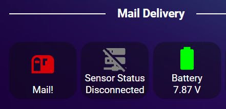
You can use the sensors and other entities as desired to add cards to your Lovelace front end:
This has been one of my favorite Home Assistant automations and has been in use for about a year. Let me know in the comments if you have thoughts or questions. In addition, you can view a YouTube video of the build and installation on my YouTube channel Resinchem Tech.
Supporting this blog and related YouTube channel
If you'd like to support future content on this blog and the related YouTube channel, or just say thanks for something that helped you out, you can use any of my Amazon links to make a purchase at absolutely no cost to you. Or if you prefer to say thanks directly, you can buy me a one-off cup of coffee at:
Late to the party here, but great project!
ReplyDeleteI appreciate the details you have provided and sharing the code.
This is a great starting point for a similar project I wanted to make.
Thanks!
Thanks. Glad you found it helpful. However, I should say that after struggling with battery life (and even after attempting to improve the battery.. I have a YouTube video on that attempt as well), I eventually swapped out the wifi system for a Zigbee door sensor inside the mailbox. The original system worked great.. but unfortunately it ended up requiring a battery swap about once a month... where the Zigbee sensor battery lasts 6-8 months. I just felt like I should let you know that this was the eventual result of this project. Good luck with your project!
ReplyDeleteWould it be possible to post the Lovelace Card code?
ReplyDeleteIt is kind of difficult to post YAML code here and have it maintain formatting and be usable. The button used is a custom-button card (added via HACS):
Delete===================
aspect_ratio: 1.2/1
color: rgb(0,255,0)
color_type: icon
entity: input_boolean.mail_delivered
name: No Mail
state:
- color: rgb(128,128,128)
icon: mdi:mailbox
value: 'off'
- color: rgb(255,0,0)
icon: mdi:mailbox-up
name: Mail!
styles:
icon:
- animation: blink 2s ease infinite
value: 'on'
type: custom:button-card
====================
I have a separate video on using the custom button card that shows exactly how to set up a Lovelace button just like this. It might be helpful to watch that as well: https://youtu.be/5Pi21pqfbxA
Thank you
Delete