As part of my research for a larger project (coming soon), I stumbled across this small $5 sensor that can provide proximity, gesture sensing and RGB + ambient light levels. And all this with only 3 GPIO pins on the ESP32. And it can be used with both Arduino/C++ sketches or in ESPHome for you Home Assistant users.This is the APDS-9960 sensor board.
Why am I showing two different versions above (that other than color look very similar)? Because in many cases, you can find cheaper alternatives for many components over the name brand versions (e.g. Adafruit, Sparkfun, etc.) that work in an identical matter. That wasn't the case in my testing for this particular component. While I was able to modify some library files to get the cloned version to work in Arduino sketches, I could not initially get it to work with ESPHome. But the ESPHome integration expects a Sparkfun board. When I tried the Sparkfun, it worked without issue. I'll cover a bit more about the cloned boards below, including how I modified an Arduino library to make it work and why an ESPHome update also allowed my original cloned version to work.
In addition, I created a YouTube video covering the sensor and showing various bench tests. You can watch that video for an overview and then return to this article for the full details.
Parts Used
|
Part
|
Description / Notes
|
|
APDS-9960 (clone)
|
Cloned version -
Different chip ID may require modification to libraries (see below)
|
|
APDS-9960 (Sparkfun)
|
Original Sparkfun
model. Works ‘as-is’ with Sparkfun libraries and ESPHome
|
|
ESP32
|
Standard ESP32
WROOM-32. Should work with other ESP32 boards, but not tested.
|
|
USB-to-microUSB data cable
|
For flashing firmware
|
|
2.54mm Pin Headers
|
Needed if board does
not come with header pins
|
|
|
|
|
Optional Bench
Testing Parts
|
|
|
Breadboard
|
|
|
Breadboard Jumpers
|
|
|
|
|
Additional Parts Shown in YouTube video:
Some of these links may be Amazon affiliate links. Use of these links will not affect your pricing, but as an affiliate this channel may earn a small commission if you make a purchase.
Notes on different APDS-9960 Boards
There are many different variations on the APDS-9960 boards.
While "cloned" or off-brand versions of many sensors and boards can be used identically to the more costly 'name-brands', that isn't necessarily the case with the various APDS-9960 boards. The primary difference is the chip ID or identifier returned by the board. Most Arduino (and the ESPHome component) libraries check this chip ID and report an invalid board if no match is found.
Also note that you can't necessarily go by the color of the PCB. Cloned versions may also use a red PCB like Sparkfun, but may still be a clone. You will need to check the chip ID and if different from the library, a small modification may be needed.
I'll primarily be using a cloned board here so I can show how an Arduino library can easily be adapted for a different board ID. If you do opt to use a name-brand board, note that many of these come with their own Arduino Library (e.g. Adafruit, Sparkfun - links to these libraries are at the end of this article) and you should use the matching library.
I won't be trying or testing the Adafruit board simply because the JST connectors on the front of the board will prevent flush mounting I need in my project. If you use the Adafruit board however, you should be able to use the Arduino Adafruit library without modification. The board may or may not work with ESPHome. This was not tested.
Specifications
|
Sensors
|
Proximity, Gesture, separate
red, green, blue and ambient light levels
|
|
Operating Voltage
|
2.4 – 3.6V
|
|
Current Draw
|
Up to 100 mA
depending upon sensor(s) in use. Less
than 20mA when not actively sensing.
|
|
Sensing Range
|
10 – 20 cm (~4 – 8”)
|
|
Communication
Protocol
|
I2C
|
Since the operating voltage is 2.4-3.6V, and the maximum current draw is 100mA (dependent upon what features are in use and the gain settings), the APDS9960 can safely be operated directly from the 3.3V pin on the ESP32.
The board does have a very short detection range (for all modes). So this board isn't likely to replace either a dedicated distance device (like a VL53L0X or an ultrasonic HC-SR04 distance sensor) or a motion/presence detector. But for my intended purposes, I don't need true distance or occupancy.
The communication protocol is I2C, meaning we'll need two GPIO pins on the ESP32. The I2C address is normally 0x39, but it is usually printed on the back side of the board as well.
There is also an interrupt pin and, if used, will require one additional digital GPIO pin.
Pinout and ESP32 Connections
There are also two jumpers on the top side of the board that can be closed with a small solder bridge:
PS: When this jumper is closed, the IR transmitter receives it's power from the normal VCC input. When open, then an additional 3.3V connection needs to be made to the VL pin to independently power the IR LED. Providing separate power for the IR transmitter can eliminate noise in some cases and can also supply additional power for higher gain values.
I2C PU: When closed, 10K pullup resistors are applied to the I2C pins (SDA/SCL). Again, depending upon the controller you are using and your use case, you may or may not want these pullup resistors enabled. To disable/bypass, leave this jumper open.
In my case, I'm leaving both jumpers open. This means my wiring looks like this:
 |
| Click to enlarge |
I'm using the standard I2C pins of GPIO21 and GPIO22 for SDA and SCL. I connect the interrupt pin (INT) to GPIO4. You can use different pins, as long as you specify the pin used in the code or configuration file. The board is powered by the 3v3 pin from the ESP32. But since my PS jumper is open, I also need to provide 3.3V power to the VL pin for powering the IR. If your jumper is closed, omit this connection, as the IR transmitter will receive its power from the VCC pin.
Getting the Chip ID
A "true" APDS990 chip should have an ID of 0xAB. The chip ID is used by Arduino and the ESPHome component library when establishing a connection to the board. Some libraries have added some ID checks for additional boards, but your particular clone may not be accepted without modifying the valid chip ID(s).
To get the chip ID of your board (if not listed in the documentation), you can run a simple Arduino sketch to get it. If you have not used the Arduino IDE with an ESP board before, I have complete setup instructions on how to install and setup the IDE for use with ESPs and how to flash a sketch:
Once the IDE is setup and configured for your particular board and the APDS9960 has been wired to the board, you can copy/paste then upload and run the following code to get both the I2C address and the chip ID:
#include <Wire.h>
// Define APDS9960 chip ID register
#define APDS9960_ID_REG 0x92 // Chip ID register address
// Function to read chip ID from a given I2C address
uint8_t readChipID(uint8_t i2cAddress) {
Wire.beginTransmission(i2cAddress);
Wire.write(APDS9960_ID_REG); // Request chip ID register
Wire.endTransmission(false);
Wire.requestFrom(i2cAddress, (uint8_t)1);
if (Wire.available()) {
return Wire.read(); // Read chip ID
}
return 0; // Return 0 if no data (invalid or no response)
}
void setup() {
Serial.begin(115200);
delay(1000);
Serial.println("Starting I2C Scanner and Chip ID Reader");
// Initialize I2C
Wire.begin();
Wire.setClock(100000);
// Scan I2C bus for devices
Serial.println("\nScanning I2C bus...");
bool deviceFound = false;
for (uint8_t address = 0x08; address <= 0x7F; address++) {
Wire.beginTransmission(address);
uint8_t error = Wire.endTransmission();
if (error == 0) {
deviceFound = true;
Serial.print("I2C device found at address 0x");
if (address < 16) Serial.print("0");
Serial.print(address, HEX);
// Read and print chip ID
uint8_t chipID = readChipID(address);
Serial.print(" - Chip ID: 0x");
if (chipID < 16) Serial.print("0");
Serial.println(chipID, HEX);
}
}
if (!deviceFound) {
Serial.println("No I2C devices found. Check wiring or try again.");
} else {
Serial.println("\nScan complete.");
}
}
void loop() {
}
Original source code by Rui Santos & Sara Santos - Random Nerd Tutorials
When you execute this code and if communication with the sensor is successful, the I2C address and chip ID will be output to the serial monitor:
 |
"Cloned" Board Chip ID
|
 |
| SparkFun Chip ID |
Bench Testing Setup
For all bench testing (Arduino and ESPHome), the APDS-9960 sensor is wired to the ESP32 according to the above wiring diagram:
 |
| Click to enlarge |
Since my APDS-9960 board has open jumpers, I also need to connect the VL pin to the 3.3V power rail. The interrupt pin is connected to GPIO4, but this may be optional depending upon the library and if you wish to use the interrupt feature or not. The ESP32 is then connected to the PC with a microUSB data cable.
Arduino Bench Testing
All Arduino testing was completed using the cloned board (Chip ID 0x9E).
I tried three or four different Arduino libraries (linked below) with my board. I had the best luck with the Adafruit version, so that's what I'll show here. But note that all the libraries needed modification for the chip ID of my clone. But this involved a simple remarking out of a few lines of code.
Modifying the Library Chip ID (Adafruit library)
To modify the library, first install it in your Arduino environment if it isn't already installed.
Once installed, browse to the Arudino installed library location (by default, this is ../documents/Arudino/libraries/Adafruit_APDS9960_Library
Open the Adafruit_APDS9960.cpp file using any text editor. Locate the following code block (around line 100):
/* Make sure we're actually connected */
uint8_t x = read8(APDS9960_ID);
if (x != 0xAB) {
return false;
}
As you can see, it is checking for a chip ID of 0xAB. If your chip ID is different, you can either modify the chip ID (e.g. replace 0xAB with 0x9E or whatever ID your chip reports):
/* Make sure we're actually connected */
uint8_t x = read8(APDS9960_ID);
if (x != 0x9E) {
return false;
}
Or you can simply remark out this section and bypass the check altogether:
/* Make sure we're actually connected */
/*
uint8_t x = read8(APDS9960_ID);
if (x != 0xAB) {
return false;
}
*/
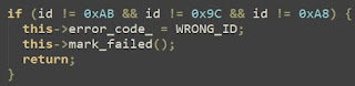
Save your changes and exit the text editor. If using another library, there may be similar checks or chip IDs that you need to modify. For example, here is the code from the .h file for the Sparkfun library:
/* Acceptable device IDs */
#define APDS9960_ID_1 0xAB
#define APDS9960_ID_2 0x9C //change to 0x9E
#define APDS9960_ID_3 0xA8
This library checks for, and allows, three different chip IDs. If your ID is different, simply change one of the three IDs to match your board.
For the following examples/bench tests, I will be using the Adafruit library with the chip ID check remarked out as shown above.
The library (and many others) come with examples. I'll be using the examples "as-is" unless otherwise noted, so I won't be showing any of the unmodified code here.
Proximity Testing
For the first two tests, I'll be using the proximity example included with the Adafruit Arduino library:
By default, the proximity example utilizes the interrupt pin which is optional. To get continuous readings, I just need to remark out the lines in the example related to the interrupt:
//set the interrupt threshold to fire when proximity > 175
// apds.setProximityInterruptThreshold(0, 175);
//enable the proximity interrupt
// apds.enableProximityInterrupt();
}
void loop() {
//print the proximity reading when the interrupt pin goes low
// if(!digitalRead(INT_PIN)){
Serial.println(apds.readProximity());
delay(500);
//clear the interrupt
// apds.clearInterrupt();
// }
The lines highlighted in red should be remarked out (add // before each line) and the line in green was added (just to avoid flooding the serial port). Once uploaded to the ESP32, the serial monitor can be used to watch the output.
 |
| Click to enlarge |
In the serial monitor, you should see the value increase as you move your hand closer to the sensor. And the value will decrease as you move farther away from the sensor. The sensor range is 0 - 255.
Proximity Interrupt
The proximity interrupt can be used to define a range where the proximity will be reported and ignored (no value) when outside of this range. This can easily be converted into a binary value. Once again, the same example code will be used except the previously remarked out lines will be restored (or just reload the original example).
In the example, you can use setProximityInterruptThreshold to restrict the range where proximity is measured/reported. I made the following changes to the default example for my testing:
//set interrupt threshold to fire when proximity > 65
apds.setProximityInterruptThreshold(0, 65);
This means that proximity will only be read/reported when the proximity range is greater than 65 (remember that closer to the sensor is a higher value). To make this more like a binary sensor, I also modified the output in the main loop:
void loop() {
//print proximity reading when the interrupt pin goes low
if(!digitalRead(INT_PIN)){
Serial.println("Clear");
//clear the interrupt
apds.clearInterrupt();
} else {}
Serial.print("Detected");
Serial.println(apds.readProximity());
delay(500);
}
}
When uploaded to the ESP32, the serial monitor will show "Detected" when moving my hand within the specified proximity range (I'm also outputting the actual value for testing) or "Clear" when nothing is within range.
 |
| Click to enlarge |
Again, I could easily create a function that returns True/False and make this a binary sensor that reports True when an object is detected within the specified range and False otherwise.
Gesture Testing
For gesture testing, I simply used the example as provided with no modifications:
This example simply returns the direction of movement across the sensor (and within range of the proximity sensor).
 |
| Click to enlarge |
While the example does not make use of the proximity interrupt, you can add it like the previous example and limit the gesture detection to movement only within a certain range. I did observe some minor inconsistencies when I moved my hand too rapidly (or even too slow). But otherwise, the gesture detection example worked well without modification. Again, you could also modify the example to return boolean values for each of the cardinal directions.
Also note that some libraries provide a NEAR and FAR direction. NEAR is returned when an object is moving towards the sensor and FAR when moving away from the sensor. Check the library documentation to see if these additional directions are available.
RGB/Ambient Light Testing
For color and ambient light levels I once again used the default example, without modification:
As soon as the example is flashed to the ESP32, the serial monitor will begin outputting red, green, blue and 'clear' (ambient) light levels.
 |
| Click to enlarge |
As you can see from the sample output, I initially was just getting ambient light values. When I used a bright LED flashlight, all values jumped up to the maximum value of 4097. This means the range for RGB/Clear runs from 0 - 4097.
I also tested various colors by using a solid color square on my cell phone.
 |
| Click to enlarge |
As you can see, when the red square was placed over the sensor, the red value jumped significantly. As expected the 'clear' or ambient light level also jumped. The blue and green values also increase slightly because even though this is a red square, traces of blue and green are also present in this particular image.
This only provides the basics. This particular library has additional functionality for things like setting the boost/gain on the IR and ADC sensors. Check out the links at the end of this article for the various libraries, where you can find a full list of features.
ESPHome Bench Testing
Like the Arduino libraries, ESPHome also checks the chip ID. This is based on the Sparkfun library and versions of ESPHome prior to 2025.7 only permitted the same three chip IDs:
 |
| ESPHome 2025.6 and earlier |
If you create and install an ESPHome node and your ID isn't one of the ones listed, then you will see the following error in the ESPHome log:
Fortunately, the latest release of ESPHome (2025.7 at time of publication) adds an additional chip ID of 0x9E which is the ID of many clones, including mine.
 |
| ESPHome 2025.7 and later |
If you still have a different chip ID, then you will need to download and modify this component source much like the Arduino libraries and then include it as an external component or library. See the ESPHome documentation for more details.
Installing ESPHome within Home Assistant and the process for creating a new device configuration (aka node) is beyond the scope of this article and I've covered it in other videos/articles, so I won't repeat it here. If you've never used ESPHome, check out the link at the end of this article for getting started.
The ESPHome configuration is a bit long to include here, but you can see the full code I used in this Github Gist file. In essence, sensors are created for each of the reported data points from the APDS-9960
Sensors:
- Red (0-4097)
- Blue (0-4097)
- Green (0-4097)
- Clear/Ambient (0-4097)
- Proximity (0-255)
Binary Sensors - Gestures (true/false):Once successfully installed onto your ESPHome, a new device is automatically discovered in Home Assistant (Settings >> Devices & Services):
Once added, the new device can be found under the ESPHome integration (on the same page as the discovered device).
 |
| Device Info - Click to enlarge |
Naturally, you can rename and/or add any or all of these entities to a dashboard:
 |
| A simple example dashboard |
What's more, the entities can now be used in your Home Assistant automations and scripts. As a basic example, you might add the following automations for controlling a light with gestures:
 |
| Turn on a light when swiping UP |
 |
| Turn off a light when swiping DOWN |
 |
| Increase brightness by 20% when swiping RIGHT |
 |
| Decrease brightness by 20% when swiping LEFT |
Of course you could add conditions to these automations as well. For example, you could use the ambient light level and specify that the light actions should only occur if the light level is below a certain value. These are just a couple of simple examples of things that can be done.
Additional Thoughts
This project is a good example of situations where a cloned board may not behave the same as 'brand name' boards. But it also shows that in some situations, a library or firmware can be slightly modified to work with clones.
In addition, the APDS-9960 isn't truly a distance sensor (since proximity is reported as 0 - 255, in reverse order). It also isn't a motion or presence detector.. or at least not a good one since the range is only around 4" - 8" (10-20 cm). And there are also light level sensors that probably do a better job. So you could use more precise individual components for these features, but as a single, quarter-sized $5 device, it can be a great option if you just need nearby proximity, simple gesture and basic light levels.
It is (hopefully) an ideal solution for my planned larger project. When (if) I ever get that project completed, I'll add a link here so that you can see how I'm implementing the sensor.
Until that time, thanks so much for reading. Feel free to let me know your thoughts (or if you've used one in your own project) down in the comment!
Links and Additional Info
Supporting this blog and related YouTube channel
It takes significant time and effort (and often expense) to create these articles and videos. If you'd like to support future content on this blog and the related
YouTube channel, or just say thanks for something that helped you out, you can consider buying me a one-off cup of coffee or two at:


No comments:
Post a Comment
To help eliminate spam and to keep all conversations civil, submitted comments are moderated. Therefore your post may not show up immediately. Please be patient as most reviews are completed within a few hours.